
Display device

a display device and touch panel technology, applied in cross-talk/noise/interference reduction, instruments, optics, etc., can solve problems such as erroneous operation of the touch panel, and achieve the effect of excellent detection sensitivity and high reliability

Active Publication Date: 2010-02-11
JAPAN DISPLAY INC +1
View PDF12 Cites 134 Cited by
  • Summary
  • Abstract
  • Description
  • Claims
  • Application Information

AI Technical Summary

Benefits of technology

[0022]To briefly explain the advantageous effects acquired by typical inventions among the inventions disclosed in this specification, they are as follows.
[0023]According to the present invention, it is possible to provide a display device having a highly reliable electrostatic capacitive type touch panel which allows finger touch inputting and possesses excellent detection sensitivity.

Problems solved by technology

To the contrary, when the sufficient capacitance ratio cannot be ensured, the touch panel cannot recognize that the finger or the like touches the touch panel and hence, there may be a possibility that the touch panel erroneously operates.

Method used


Image

  • Display device
  • Display device
  • Display device

Examples


Embodiment Construction

[0033]Hereinafter, an embodiment of the present invention is explained in detail in conjunction with drawings.

[0034]Here, in all drawings for explaining the embodiment, parts having identical functions are given same symbols, and their repeated explanation is omitted.

[0035]In this embodiment, the explanation is made with respect to a case in which a liquid crystal display panel is used as one example of a display panel. Here, the present invention is applicable to any display panel which can mount a touch panel thereon. Further, the display panel is not limited to the liquid crystal display panel, and the display panel may be a display panel which uses organic light emitting diode elements (OLED) or surface conductive electron emission elements (FED).

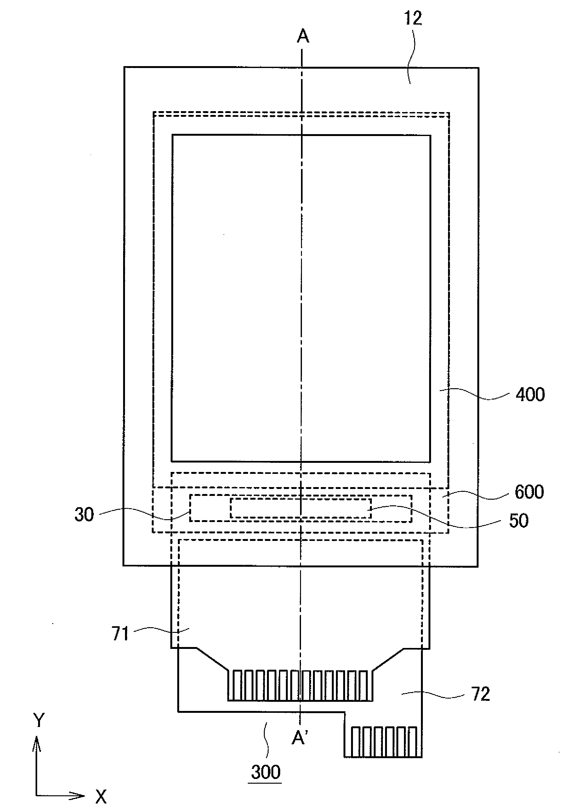
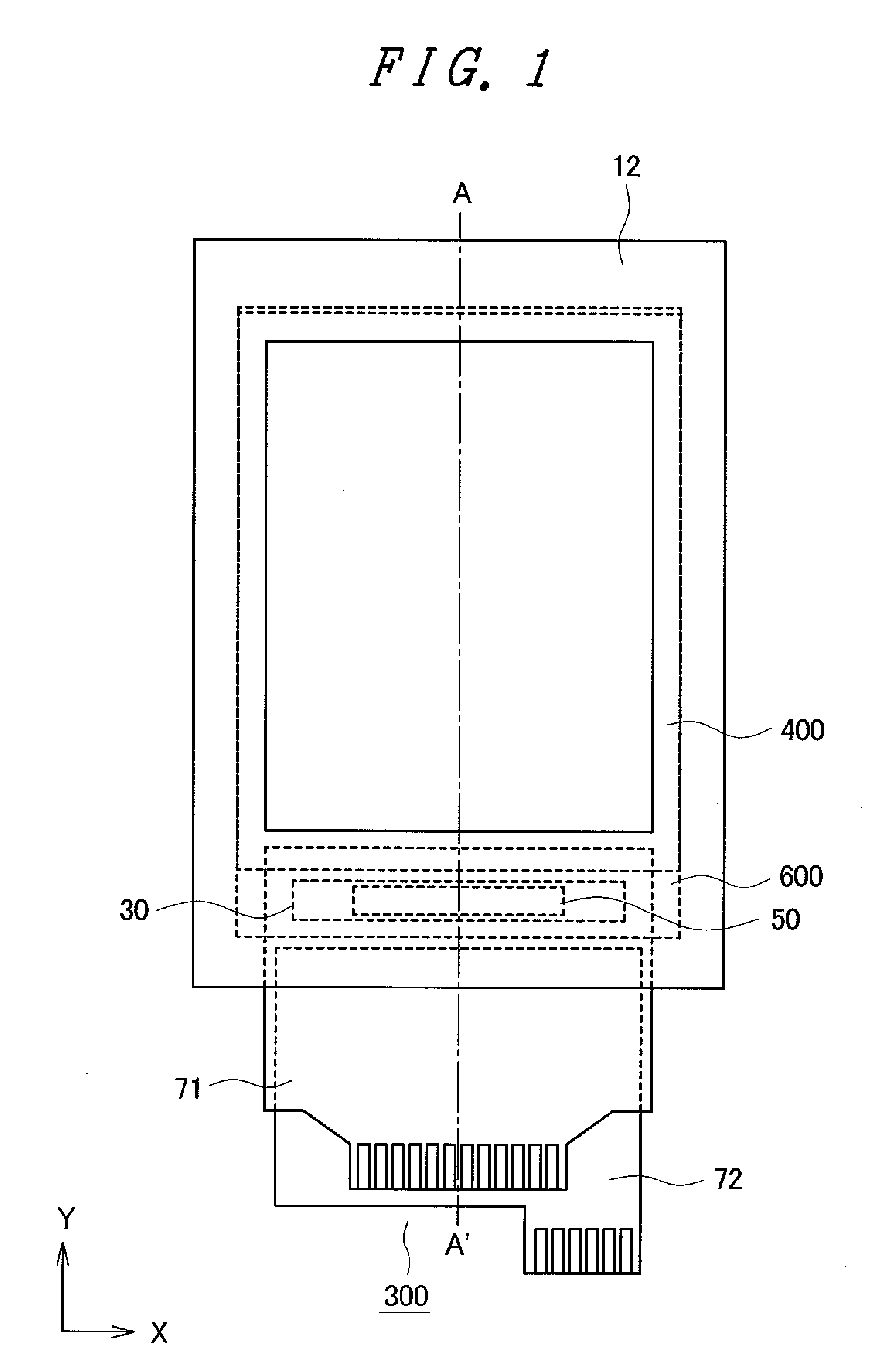
[0036]FIG. 1 is a plan view showing the schematic constitution of a display device having a touch panel according to the embodiment of the present invention. FIG. 2 is across-sectional view taken along a line A-A′ in FIG. 1.

[0037]The di...


PUM


Abstract

A display device having a highly reliable electrostatic capacitive type touch panel which allows finger touch inputting and possesses excellent detection sensitivity is provided. With respect to X electrodes and Y electrodes which are formed on an electrostatic capacitive type touch panel, either one of the X electrodes and the Y electrodes is divided corresponding to a ratio between the number of X electrodes and the number of Y electrodes, and a floating electrode is formed in gaps formed along with the reduction of area of the electrode thus adjusting the area of the electrode. Due to the contraction of the area of the individual electrode, a noise level can be lowered more compared to lowering of a signal level and hence, an S / N ratio can be increased thus enhancing the detection sensitivity. Further, a line is branched on a flexible printed circuit board, intersecting lines are formed on a back surface of the flexible printed circuit board, and the intersecting lines are arranged to orthogonally intersect with lines formed on a front surface of the flexible printed circuit board thus lowering line capacitance.

Description

CROSS-REFERENCE TO RELATED APPLICATION[0001]The present application claims priority from Japanese application JP2008-202870 filed on Aug. 6, 2008, the content of which is hereby incorporated by reference into this application.BACKGROUND OF THE INVENTION[0002]1. Field of the Invention[0003]The present invention relates to a display device with a touch panel, and more particularly to a technique which is effectively applicable to a display device with a touch panel which includes an electrostatic capacitive type touch panel.[0004]2. Description of the Related Art[0005]Recently, a touch panel technique which assists a “user-friendly” graphical user interface has become important in the propagation of mobile equipment.[0006]For example, as a touch panel technique, JP-T-2003-511799 (patent document 1) discloses an electrostatic capacitive type touch panel. With respect to such an electrostatic capacitive type touch panel, there has been known the touch panel which can detect a touch posi...

Claims


Application Information

Patent Timeline
Patent Type & Authority Applications(United States)
IPC IPC(8): G06F3/041
CPCG06F3/0418G06F3/044G06F2203/04111H05K2201/09254H05K3/361H05K2201/09245H05K1/118G06F3/04164G06F3/0446G06F3/0416G06F2203/04102G06F1/16G06F3/0412G06F2203/04103H05K1/0216H05K1/11G02F1/133345G02F1/13338G02F1/13439G06F2203/04107
Inventor HASHIMOTO, SHINYA
Owner JAPAN DISPLAY INC
Learn More