
Uplink resource control

Inactive Publication Date: 2010-02-04
ALVARION
View PDF13 Cites 20 Cited by
  • Summary
  • Abstract
  • Description
  • Claims
  • Application Information

AI Technical Summary

Benefits of technology

[0026]controlling uplink resources to said respective mobile units to minimize uplink interference to surrounding base stations, said minimizing being based on said obtained measures.

Problems solved by technology

However, ignoring interference to other base stations reduces deployment capacity.
Additionally, interference with neighboring base stations is strongly dependent on the location of the mobile station with respect to the neighboring base station.
A mobile station that is equidistant from two base stations may cause considerable interference with the equally distant base station it is not communicating with.
Thus the setting of a fixed maximum power level to avoid interference is very wasteful for those mobile stations not currently in interference-causing locations.
Keeping each mobile station as quiet as possible provides an unnecessary limitation on the data rate that can be provided, and thus artificially and unnecessarily limits the power of wireless systems to provide broadband.

Method used


Image

  • Uplink resource control
  • Uplink resource control
  • Uplink resource control

Examples


first embodiment

[0061]In a first embodiment, the parameter used to obtain the interference is the carrier-interference and noise ratio CINR. It is noted that the CINR is neither the carrier to noise ratio (CNR) nor the carrier to interference ratio (CIR) but is a hybrid of the two, as follows:

[0062]The carrier-to-interference ratio (C / I, CIR), is the quotient between the average received modulated carrier power S or C and the average received co-channel interference power I, i.e. cross-talk, from other transmitters than the useful signal.

[0063]The CIR resembles the carrier-to-noise ratio (CNR or C / N), which is the signal-to-noise ratio (SNR or S / N) of a modulated signal before demodulation.

[0064]The CIR ratio is studied in interference limited systems, i.e. where I dominates over N, typically in cellular radio systems and broadcasting systems where frequency channels are reused in order to achieve high level of area coverage. The C / N is studied in noise limited systems. If both situations can occur...

third embodiment

[0067]A third embodiment uses a combination of the above two systems. CINR is measured in the short term to provide real time measurements for fast adaptation of the system. Then handover data is used when available to calibrate the CINR.

[0068]The embodiments are now considered in greater detail. A first embodiment is based on using the reported downlink CINR as an estimate of the ratio between the desired signal (signal level received at the serving BS) and the total outgoing interference signal (signal level received by the non-serving base-stations).

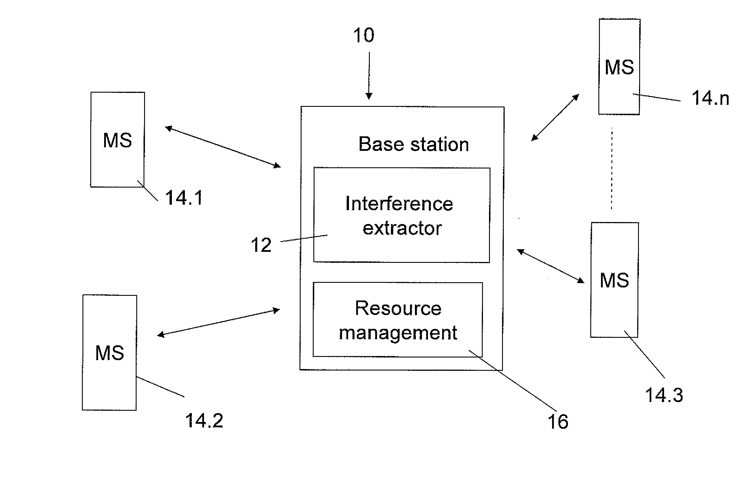
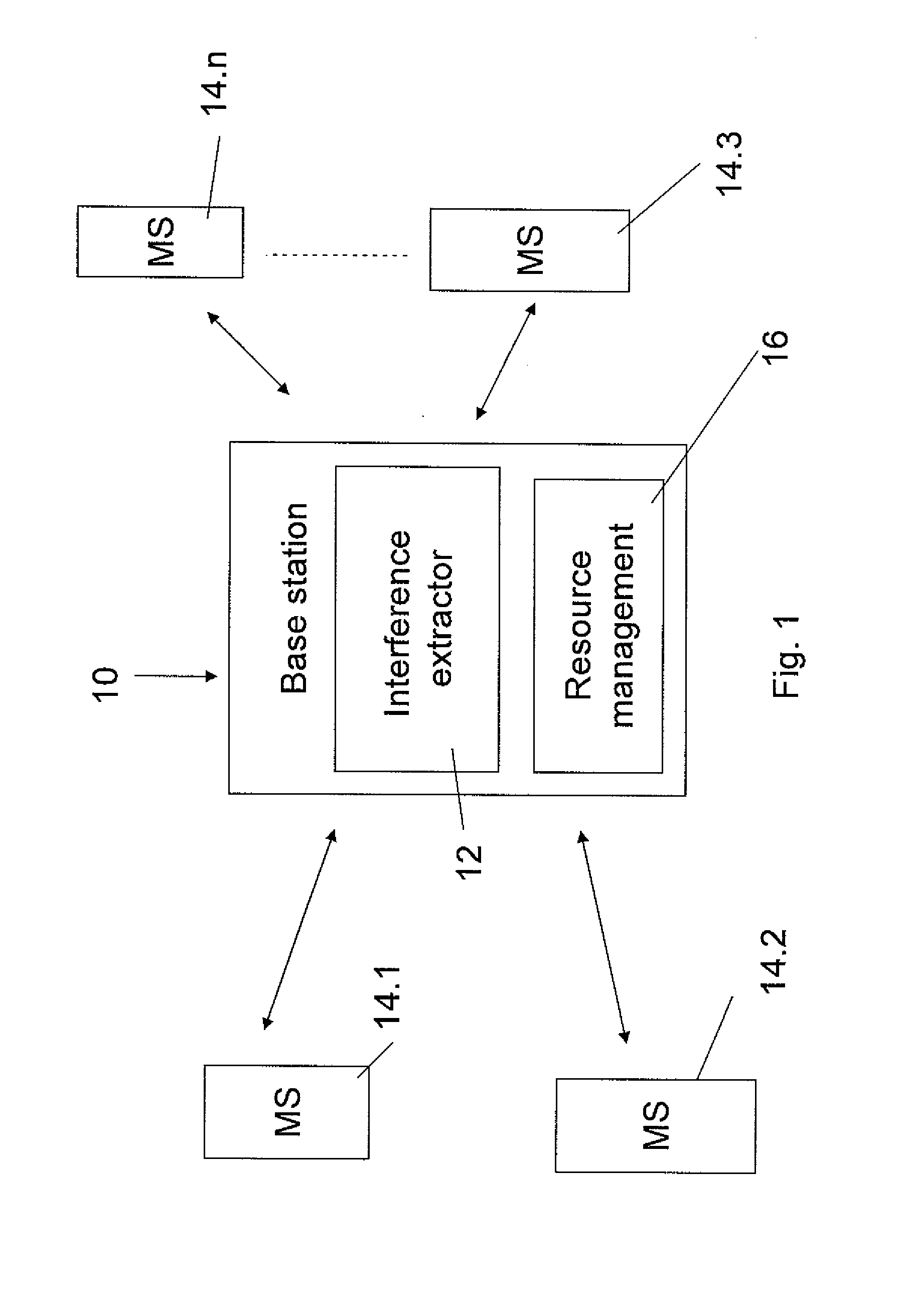
[0069]In one embodiment the total outgoing interference level estimation is used as the basis for interference budget management. For interference budget management, the RRM, or radio resource management for example at the base station, allocates power to the mobile stations based on both a total outgoing interference budget from the current base station to all other base stations and the required power that the mobile station needs f...

fourth embodiment

[0074]Reference is now made to FIG. 4, which is a simplified schematic diagram illustrating the present invention. As with FIG. 3, a proportional fair allocation unit 50 allocates resources between mobile stations 54. In this case interference 56 is optimized or budgeted against allocation of frequency channels. In general MSs are not allocated full channels but rather are allocated time slots on particular frequency channels.

[0075]In the fourth embodiment it is possible to further exploit incoming interference measurements, or even estimates if measurements are not available, by doing just in time frequency planning. That is to say mobile stations 54 are allocated with different frequency channels 60 based on the measured interference 56. Those amongst mobile stations 54 which are in regions of higher interference are allocated to frequencies not currently in use by the neighboring base station or not especially likely to interfere with frequencies in use by the neighboring base st...


PUM


Abstract

Apparatus for interference budgeting at base stations of a wireless network wherein mobile units communicate with a current base station but may cause interference to neighboring base stations, comprises: an extraction unit for extracting, from signals received at said current base station in relation to respective mobile units, an interference indication; and an uplink management unit for controlling the uplink to mobile units, wherein said management unit is connected to said extraction unit to obtain respective interference indications, thereby to use said respective interference indications as constraints when allocating said uplink resources. The resource may be uplink power or an uplink frequency channel that is allocated to different mobile stations and / or it may be interference budget that is allocated between base stations.

Description

RELATIONSHIP TO EXISTING APPLICATIONS[0001]The present application claims benefit under 35 U.S.C. §119(e) from U.S. Provisional Patent Application No. 61 / 084,307 filed Jul. 29, 2008, the contents of which are incorporated herein by reference.FIELD AND BACKGROUND OF THE INVENTION[0002]The present invention, in some embodiments thereof, relates to a cellular communication system and, more particularly, but not exclusively, to uplink power control and even more particularly, but not exclusively, to uplink resource control.[0003]The invention belongs to the field of cellular communication and particularly to the field of uplink power control in the 802.16e, or WiMAX system. The invention may also be applicable to OFDMA multi-carrier systems 802.16 such as 16e and 16m LTE 3GPP 802.22, 802.20, Next generation PHF. The WiMAX system comprises mobile stations MS, circulating amongst a network of base stations BS. Each MS participating in the network is connected to a current BS via an uplink...

Claims


Application Information

Patent Timeline
IPC IPC(8): H04W72/04H04W52/00H04B17/00
CPCH04W24/00H04W28/04H04W72/082H04W52/24H04W52/346H04W52/146H04W72/541
Inventor REINA, GUYSTOPLER, DANNY
Owner ALVARION
Learn More