Intracavity ultrasonic probe

a technology of ultrasonic probe and intracavity, which is applied in the direction of ultrasonic/sonic/infrasonic diagnostics, instruments, catheters, etc., can solve the problems of reducing the propagation capability of ultrasonic waves, affecting the accuracy of ultrasonic images, so as to prolong the life of intracavity ultrasonic probe and achieve high-quality ultrasonic images. , the effect o

Inactive Publication Date: 2010-02-04
FUJIFILM CORP
View PDF9 Cites 5 Cited by
  • Summary
  • Abstract
  • Description
  • Claims
  • Application Information

AI Technical Summary

Benefits of technology

[0022]According to the one aspect of the present invention, in the intracavity ultrasonic probe to be used in an ultrasonic endoscope or the like, a sulfur component is trapped by the sulfur adsorbing material before the sulfur component dissolved in liquid within an intermediate balloon made of rubber corrodes an electrode. It is therefore pos

Problems solved by technology

Further, in the case of a piezoelectric vibrator employing a piezoelectric ceramic as the piezoelectric material, there is a large difference between the acoustic impedance of the vibrator 102 and the acoustic impedance of a human body or the like, and reflection of ultrasonic waves will occur at the boundary surface therebetween, resulting in a propagation loss.
In the case of using an intracavity ultrasonic probe 100 within the body such as a digestive organ or a bronchus, if there is an air gap in the propagation path of ultrasonic waves, the propagation capability of ultrasonic waves will decrease significantly, thereby making the measurement difficult.
Silver sulfide is an insulating material, which causes an increase in the resistance or disconnection of the electrode 102c, resulting in a reductio

Method used


Image

  • Intracavity ultrasonic probe
  • Intracavity ultrasonic probe
  • Intracavity ultrasonic probe

Examples


Embodiment Construction

[0030]Hereinafter, embodiments of the present invention will be described in detail with reference to the drawings. The same reference numerals will be assigned to the same component elements and the description thereof will be omitted.

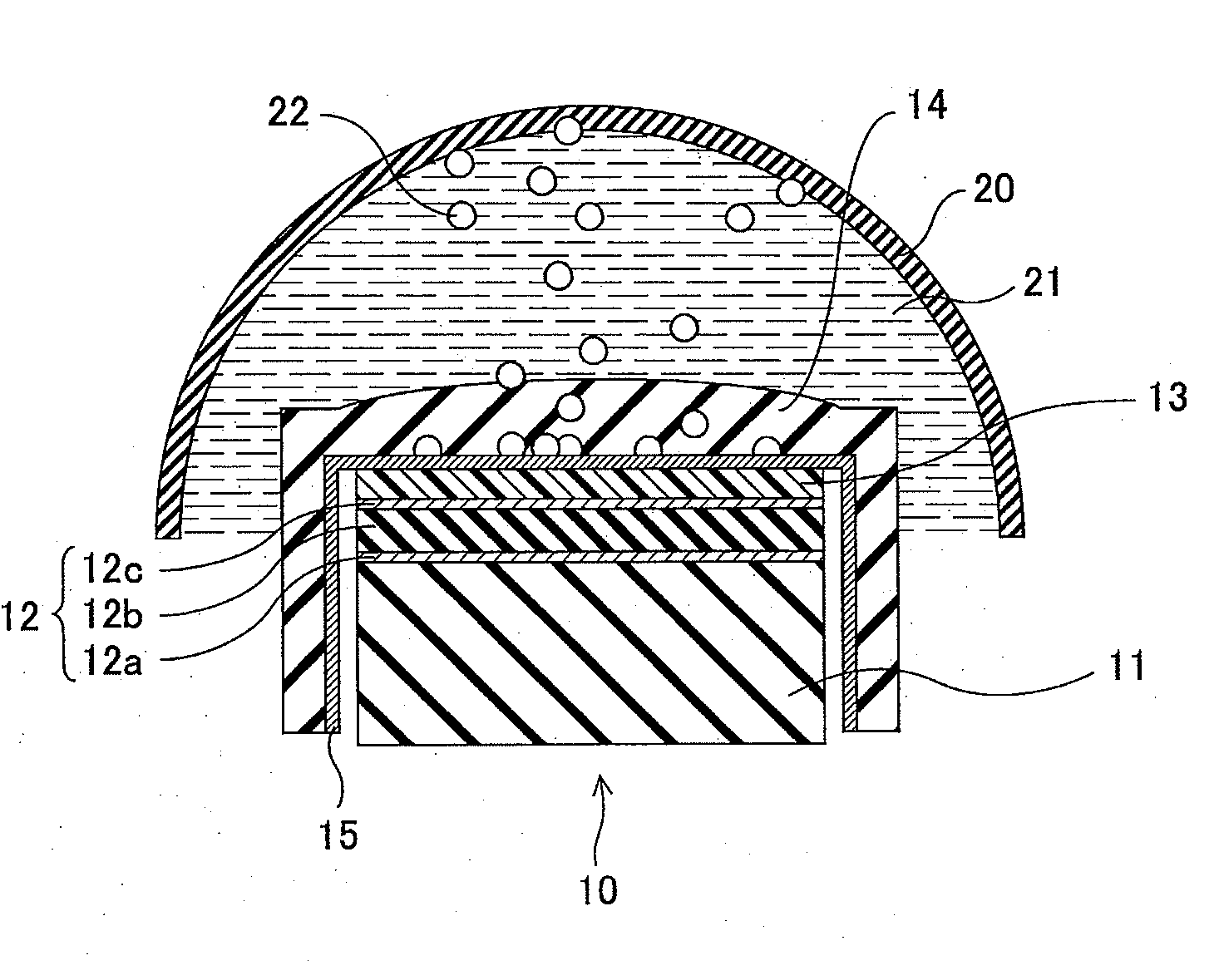
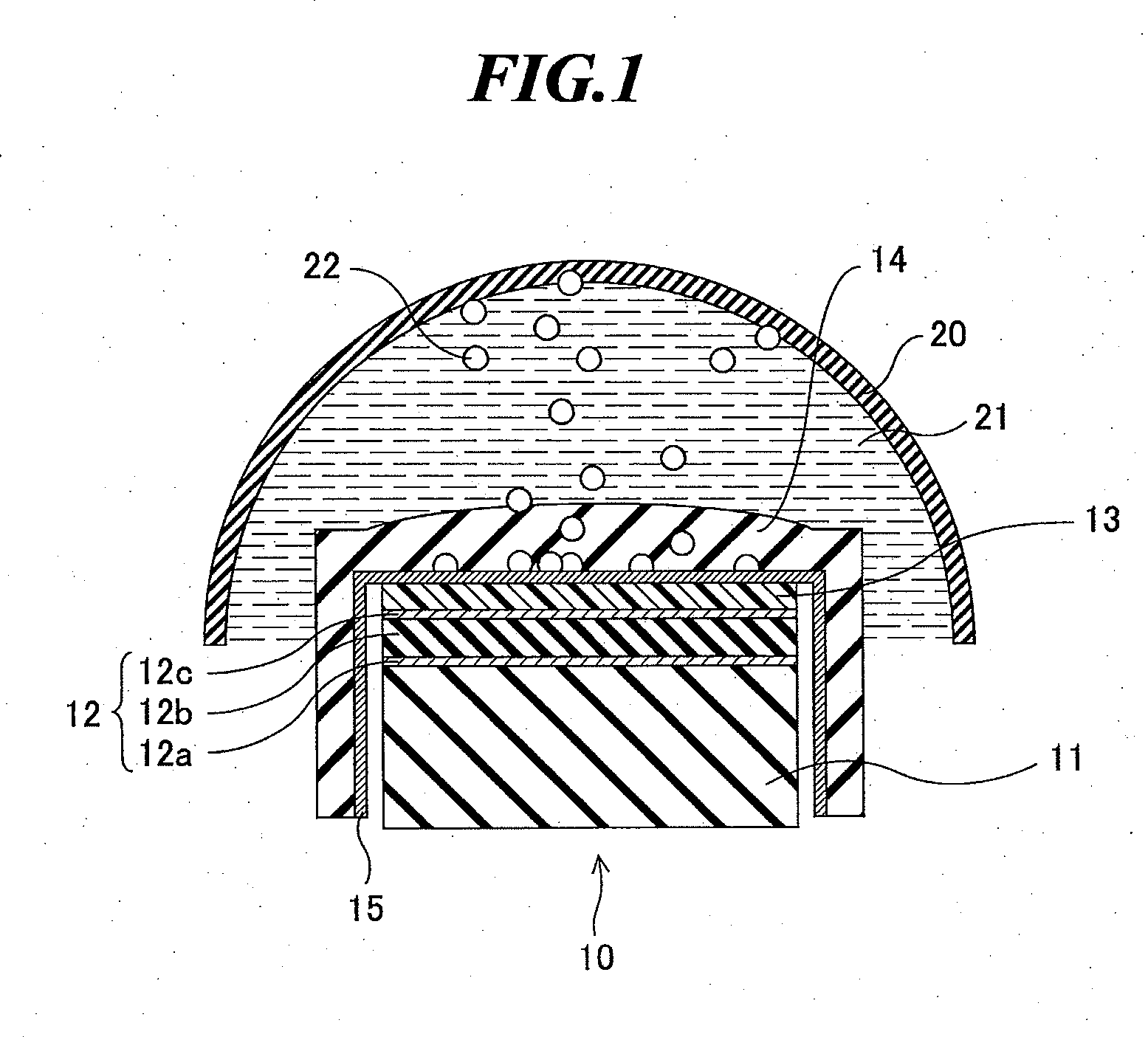
[0031]FIG. 1 is a cross sectional view schematically showing a use state of an intracavity ultrasonic probe according to a first embodiment of the present invention. This intracavity ultrasonic probe is to be used in an ultrasonic endoscope, for example. As shown in FIG. 1, an intracavity ultrasonic probe 10 includes a plurality of piezoelectric vibrators 12, at least one acoustic matching layer 13 provided above the plurality of piezoelectric vibrators 12, an acoustic lens 14 disposed above the at least one acoustic matching layer 13 so as to cover the at least one acoustic matching layer 13 and the plurality of piezoelectric vibrators 12. The plurality of piezoelectric vibrators 12 are supported by a backing material 11 formed to have a convex shape...


PUM


Abstract

An intracavity ultrasonic probe which prevents or reduces degradation or failures with time due to use of an intermediate balloon made of rubber. The intracavity ultrasonic probe includes: a piezoelectric vibrator having a piezoelectric material, and a first electrode layer and a second electrode layer formed on a first surface and a second surface of the piezoelectric material, respectively; at least one acoustic matching layer provided above the second electrode layer; an acoustic lens disposed above the at least one acoustic matching layer so as to cover the at least one acoustic matching layer and the piezoelectric vibrator; and a sulfur adsorbing material layer disposed between the acoustic lens and the second electrode layer.

Description

CROSS-REFERENCE TO RELATED APPLICATION[0001]The present application claims priority from Japanese Patent Application No. 2008-196291 filed on Jul. 30, 2008, the contents of which are incorporated herein by reference in their entirety.BACKGROUND OF THE INVENTION[0002]1. Field of the Invention[0003]The present invention relates to an ultrasonic probe to be used for intracavity examination in an ultrasonic endoscope or the like, and in particular, relates to a structure for preventing corrosion of an electrode of a piezoelectric vibrator of an intracavity ultrasonic probe.[0004]2. Description of a Related Art[0005]Ultrasonic imaging is an image generation technology utilizing the nature of ultrasonic waves that the ultrasonic waves are reflected at a boundary between regions with different acoustic impedances. The ultrasonic imaging for acquiring internal information of an object to be inspected by transmitting and receiving ultrasonic waves has been utilized in a wide range of departm...

Claims


Application Information

Patent Timeline
IPC IPC(8): H01L41/053G10K9/122
CPCA61B8/08A61B8/12A61B8/445G10K11/004A61B8/4483
Inventor OSAWA, ATSUSHI
Owner FUJIFILM CORP
Why Eureka
Try Eureka