Electric power conversion circuit, and control device for multiphase electric rotary machine

Active Publication Date: 2010-01-28
DENSO CORP
View PDF8 Cites 7 Cited by
  • Summary
  • Abstract
  • Description
  • Claims
  • Application Information

AI Technical Summary

Benefits of technology

[0010]The voltage conversion means according to the present invention varies the voltage of the electric power supply means and then supplies the varied voltage to each of the phases other than the predetermined phase. This structure makes it possible to control a line voltage as a difference in voltage between the predetermined phase and each of the other phases. That is, it is possible to adjust the control values for the multiphase electric rotary machine to desired control values. In particular, because no voltage conversion means is placed for the predetermined phase of the multiphase electric rotary machine, it is possible to decrease the total number of components of the electric power conversion circuit, and also to decrease electric power loss for the predetermined phase. It is desirable to connect the predetermined phase to a node at a voltage potential of a positive electrode or a negative electrode of the electric power supply means, or a node at a voltage potential between the positive and negative electrodes of the electric power supply means.

Problems solved by technology

This often generates common-mode noises and a large surge voltage.
This increases the manufacturing cost of the electric power conversion circuit.

Method used


Image

  • Electric power conversion circuit, and control device for multiphase electric rotary machine
  • Electric power conversion circuit, and control device for multiphase electric rotary machine
  • Electric power conversion circuit, and control device for multiphase electric rotary machine

Examples


first embodiment

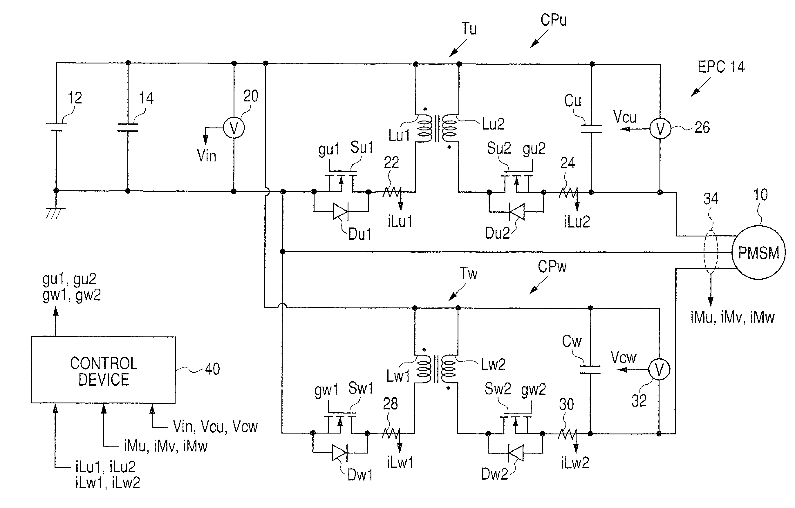
[0028]A description will be given of the control system equipped with the electric power conversion circuit (EPC) and the control device capable of controlling the operation of the EPC for the electric rotary machine 10 according to the first embodiment of the present invention with reference to FIG. 1 to FIG. 6.

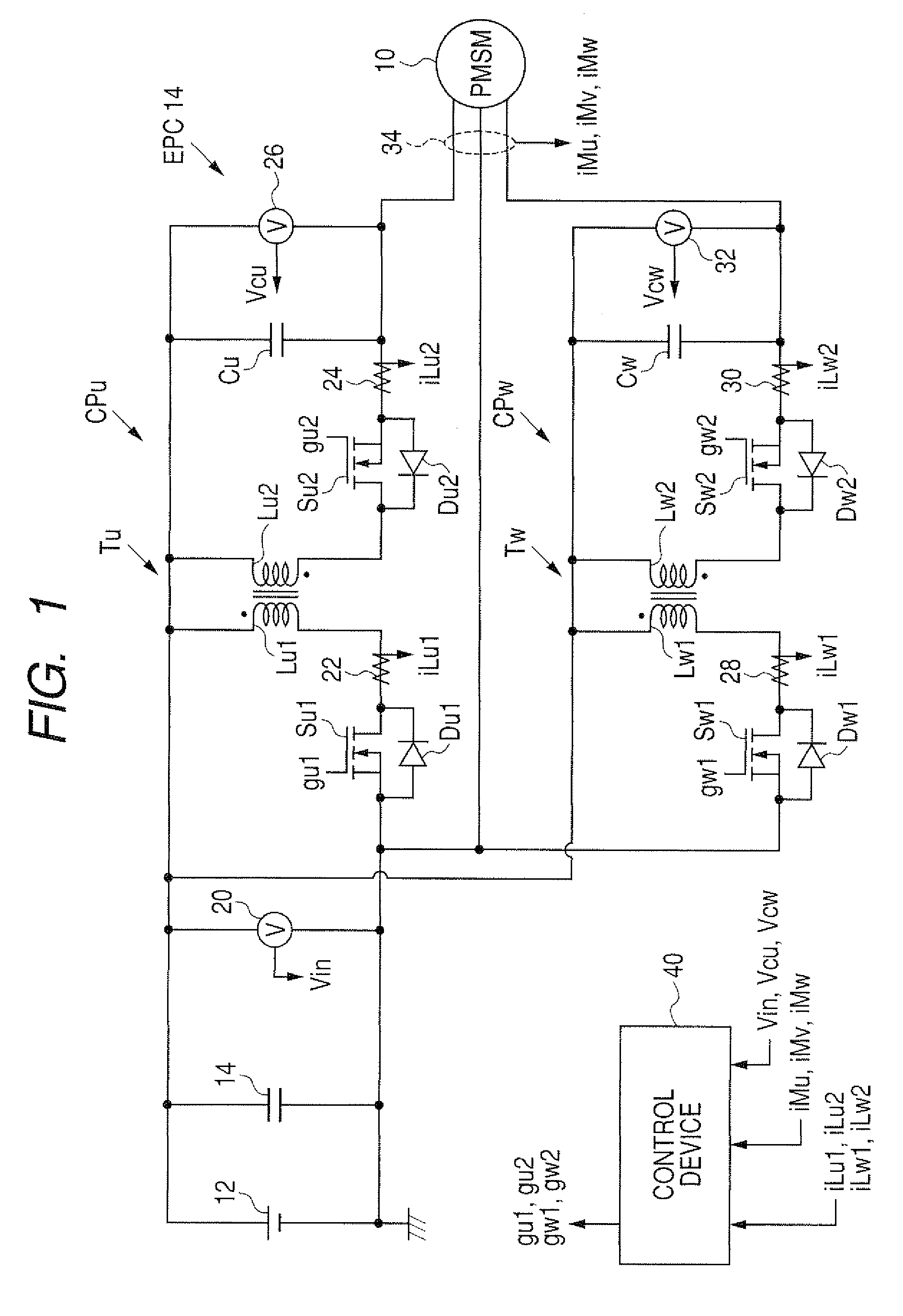
[0029]FIG. 1 is a diagram showing an entire configuration of a control system for controlling the operation of the electric rotary machine 10. The control system is comprised of the electric power conversion circuit 14, the control device 40, and the high voltage battery 12. The electric power conversion circuit 14 is comprised of a U phase part and a W phase part.

[0030]For example, the electric rotary machine 10 is an electric power generator such as a permanent magnet synchronous motor (PMSM) for use in hybrid vehicles. The electric rotary machine 10 is connected to a high voltage battery 12 through the electric power conversion circuit (EPC) 14. The battery 12 is a rechar...

second embodiment

[0120]A description will be given of the control system equipped with the electric power conversion circuit (EPC) and the control device capable of controlling the operation of the EPC for the electric rotary machine 10 according to the fourth embodiment of the present invention with reference to FIG. 7.

[0121]FIG. 7 is a diagram showing an entire configuration of the control system for controlling the operation of the electric rotary machine. The control system is comprised of the EPC, the control device, and the high voltage battery according to the second embodiment of the present invention.

[0122]In the EPC, the control device, and the high voltage battery in the control system according to the second embodiment shown in FIG. 7, the same components of the control system according to the first embodiment shown in FIG. 1 are designated with the same reference numbers and characters.

[0123]As shown in FIG. 7, in the EPU 14 for the electric rotary machine 10 according to the second emb...

third embodiment

[0128]A description will be given of the control system equipped with the electric power conversion circuit (EPC) and the control device 20 capable of controlling the operation of the EPC for the electric rotary machine 10 according to the third embodiment of the present invention with reference to FIG. 8.

[0129]FIG. 8 is a diagram showing an entire configuration of the control system for controlling the operation of the electric rotary machine 10. The control system is comprised of the EPC, the control device, and the high voltage battery 12 according to the third embodiment of the present invention.

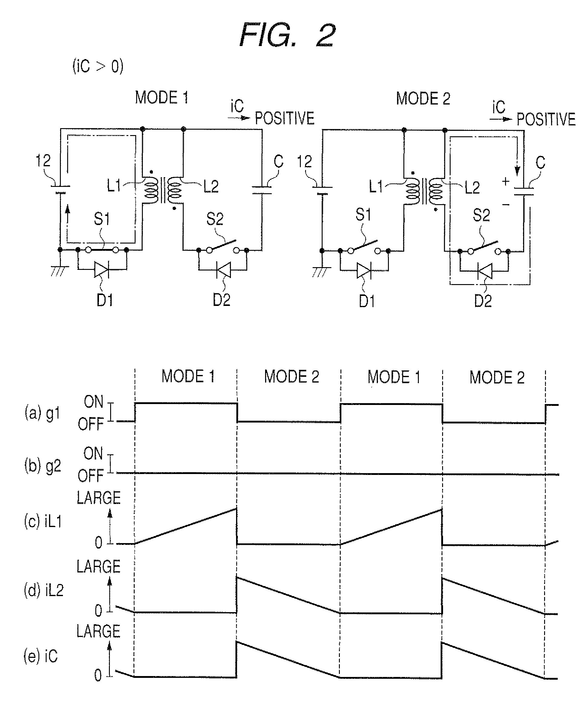
[0130]Like the second embodiment, the converter unit in the EPC according to the third embodiment is capable of adjusting the voltage potential, the boundary of which is the voltage potential at the negative electrode of the high voltage battery 12, within a range of the voltage potential at the positive electrode of the high voltage battery 12. The range of the variable voltage potentia...


PUM


Abstract

An EPC connected between a three phase motor and a battery fixes a voltage of the V phase of the three phase motor to a voltage potential of a positive electrode of the battery. A converter unit is placed for each of the U and W phases of the three phase motor. Each of the converter units has a chopper circuit part and a capacitor Each of the converter units converts the voltage of the battery to a desired voltage. The voltage of each of V and W phases is adjusted until the voltage of being twice of the voltage of the battery based on the voltage potential at the positive electrode of the battery as a reference voltage. This makes it possible to adjust the absolute value of a line voltage between V and W phases until the voltage of the battery as an upper limit voltage.

Description

CROSS-REFERENCE TO RELATED APPLICATION[0001]This application is related to and claims priority from Japanese Patent Application No. 2008-193272 filed on Jul. 28, 2008, the contents of which are hereby incorporated by reference.BACKGROUND OF THE INVENTION[0002]1. Field of the Invention[0003]The present invention relates to an electric power conversion circuit connected between an electric power supply source (such as a battery) and a multiphase electric rotary machine, and further relates to a control device for controlling the electric power conversion circuit to adjust control values for the multiphase electric rotary machine.[0004]2. Description of the Related Art[0005]It is known to control a switching element for an inverter unit based on a comparison result between an instruction voltage and a carrier wave to be supplied to an electric rotary machine as a control target. In the control operation, the inverter unit can supply an instruction voltage of an approximate sine curve t...

Claims


Application Information

Patent Timeline
IPC IPC(8): H02P27/06
CPCH02M7/4807H02M7/493H02M7/49H02P27/06H02M3/1582
Inventor KIMURA, TOMONORI
Owner DENSO CORP
Why Eureka
Try Eureka