
Land application vehicle, loading apparatus and material handling system and method for semi-solid material

a technology of semi-solid materials and loading apparatus, applied in the direction of manure treatment, sowing, loading/unloading, etc., can solve the problems of not being suitable for application using a conventional manure spreader, and increasing the shipping weight of sludge, so as to achieve the effect of reducing odour and nutrient loss

Inactive Publication Date: 2010-01-28
NUHN INDS
View PDF5 Cites 3 Cited by
  • Summary
  • Abstract
  • Description
  • Claims
  • Application Information

AI Technical Summary

Benefits of technology

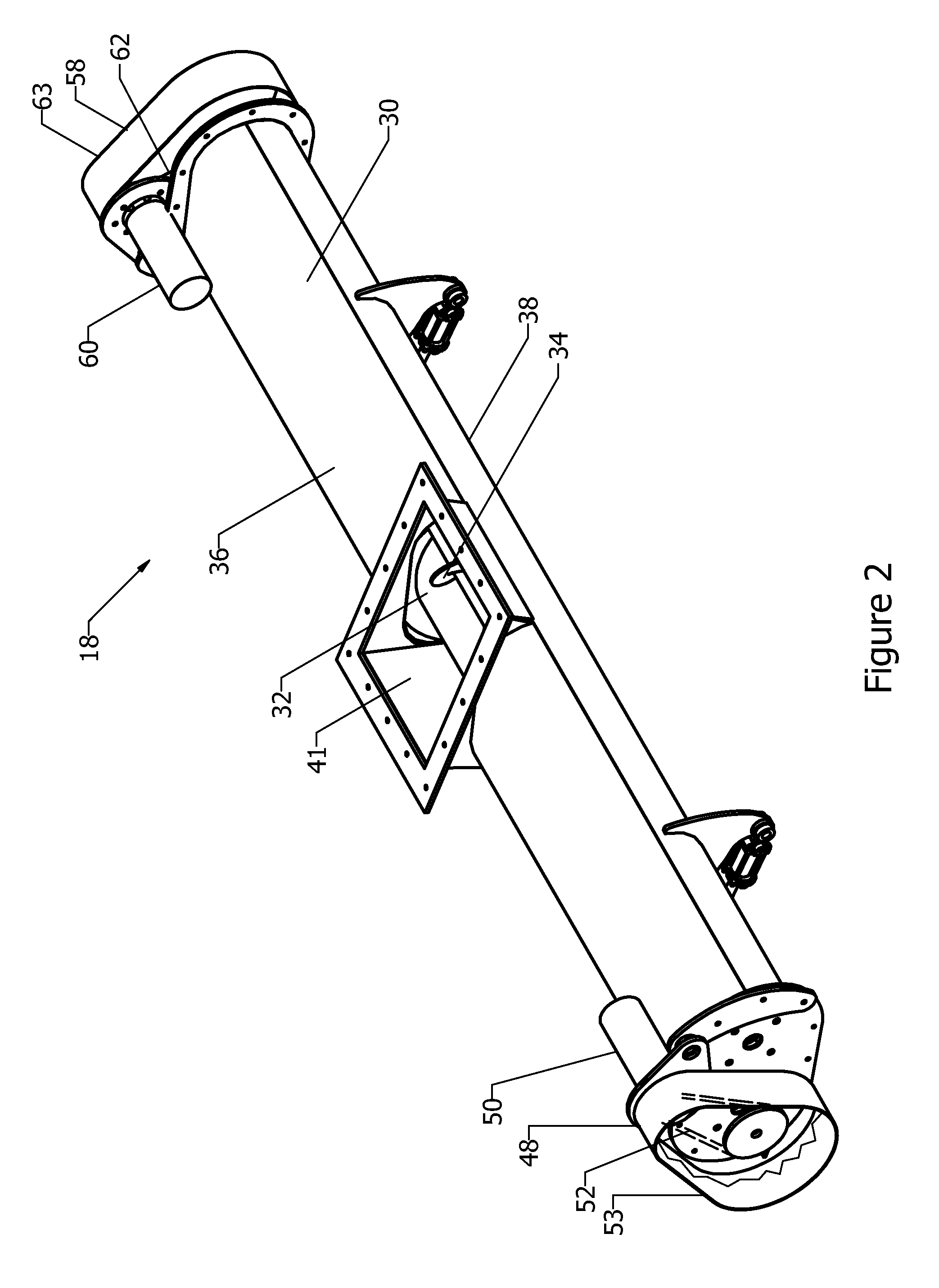
[0010]The distributor may comprise a pair of transverse augers that may have continuous, oppositely oriented flights; in this embodiment, the augers are co-rotated (rotated in the same direction). In an alternative embodiment, the flights are oriented in the same direction and the augers are counter-rotated (rotated in opposite directions). The mutually opposed material transfer orientation of the augers creates recirculation to prevent packing of the semi-solid material within the distributor housing and the associated power loss and uneven distribution of semi-solid material that would result therefrom.
[0011]The first distributor auger may be positioned within the housing and configured for transferring the semi-solid materials towards the distributor outlet. In one embodiment, only the first distributor auger is so positioned and configured. The augers may or may not be intermeshing; intermeshing is advantageous in that it creates additional shear and aids in creating recirculation and self-cleaning of the augers. The first distributor auger may be located slightly below and rearward of the second distributor auger. The distributor outlet may comprise a plurality of discrete openings (e.g. five openings) provided in the bottom of the distributor housing evenly transversely spaced along the length of the distributor and proximal the first distributor auger in order that the semi-solid material can fall out on top of the ground beneath the distributor.
[0012]The speed of the augers may be adjusted to obtain distribution of the solids along the distributor, while at the same time creating enough shear to force the solids out through the distributor outlet. The speed adjustment may take into account the application rate and the quality of the semi-solid material (in terms of stickiness and water content). In one embodiment, each auger may be rotated at a different speed. The first distributor auger may rotate at a slower rate than that of the second distributor auger. The speed of the two augers may be adjusted in order to provide even distribution of semi-solid materials along the distributor while at the same time providing the desired amount of recirculation to prevent packing of the semi-solid material at the ends of the housing.
[0013]A soil incorporator may be optionally installed rearward of the applicator that comprises a plurality of earth working tools positioned and configured for covering the semi-solid material discharged onto the ground through the distributor outlets with earth. The earth working tools are designed to throw dirt over top of each strip of manure discharged from the distributor outlets. In this way, the strips are covered with soil in order to minimize odour and nutrient loss. The earth working tools may comprise a plurality of coulter wheels that may comprise at least one pair of coulter wheels, the pair comprising a first coulter wheel and a second coulter wheel. There may be a rear spacing between the first and second coulter wheels that is less than a front spacing. There may be a bottom spacing between the first and second coulter wheels that is less than a top spacing. This advantageously allows the incorporator to throw a sufficient amount of dirt to cover the semi-solid materials, without overly working the soil or creating too great of a power requirement for the vehicle towing implement.
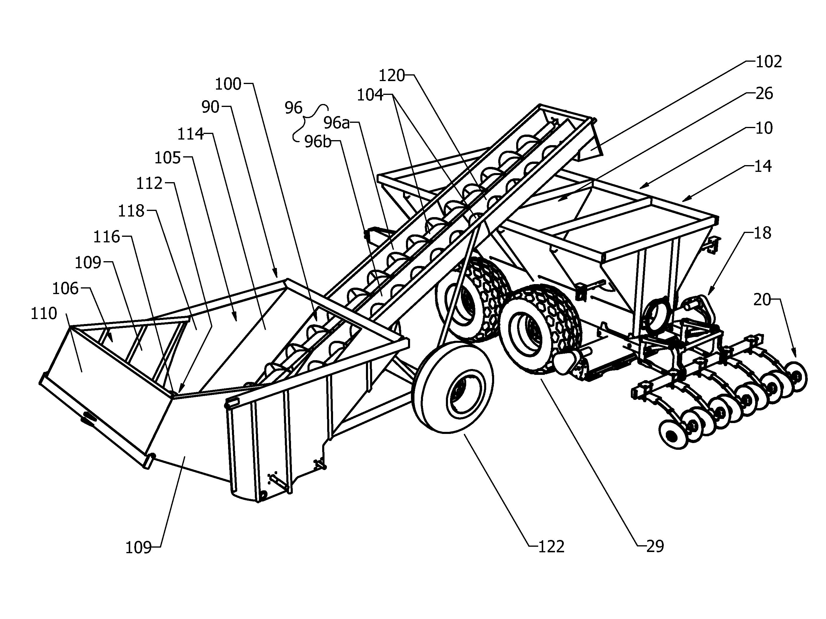
[0015]The vehicle may include some or all of the following desirable or advantageous features. The vehicle may allow for either conventional application on top of the soil or incorporation into the soil to reduce the odour and loss of desirable nutrient content through evaporation. The vehicle may be suitable to be pulled by either a truck, for highway transport, or a farm tractor, for application of the bio-solids to the field. The vehicle may be easy to fill, for example through the top of the vehicle, be easy to clean, and not be prone to plugging or sticking of any moving parts. The vehicle may be suitable for use as part of an integrated bio-solids handling system that includes means for loading the vehicle.
[0017]In one embodiment, the chamber may be equipped with a lowerable side that comprises at least an outwardly pivoting portion. The chamber may be equipped with telescoping end plates connected to the lowerable side that together form a receiving chute when pivoted outwardly. In the receiving position, the floor may be at a first angle to horizontal and, in the emptying position, the floor may be at a second angle greater than the first angle. This facilitates loading of the chamber using a dump truck or similar vehicle, since these vehicles typically are not capable of delivering their payloads into a chamber with a high lift-over height. In the emptying position, the loading wall may be oriented to direct semi-solid material generally towards the loader chute inlet.

Problems solved by technology

One of the main problems in wastewater treatment is the environmentally safe and economic disposal of sludge.
One problem with this approach is that the sludge has a very high water content, which increases the shipping weight of the sludge.
One difficulty with this approach is that the sludge is no longer amenable to handling by pumping, so different handling and land application equipment is required.
However, even when de-watered, the solids content of the sludge is lower than that of solid animal manure (i.e. there is still too much water) and would therefore not be suitable for application using a conventional manure spreader.

Method used


Image

  • Land application vehicle, loading apparatus and material handling system and method for semi-solid material
  • Land application vehicle, loading apparatus and material handling system and method for semi-solid material
  • Land application vehicle, loading apparatus and material handling system and method for semi-solid material

Examples


Embodiment Construction

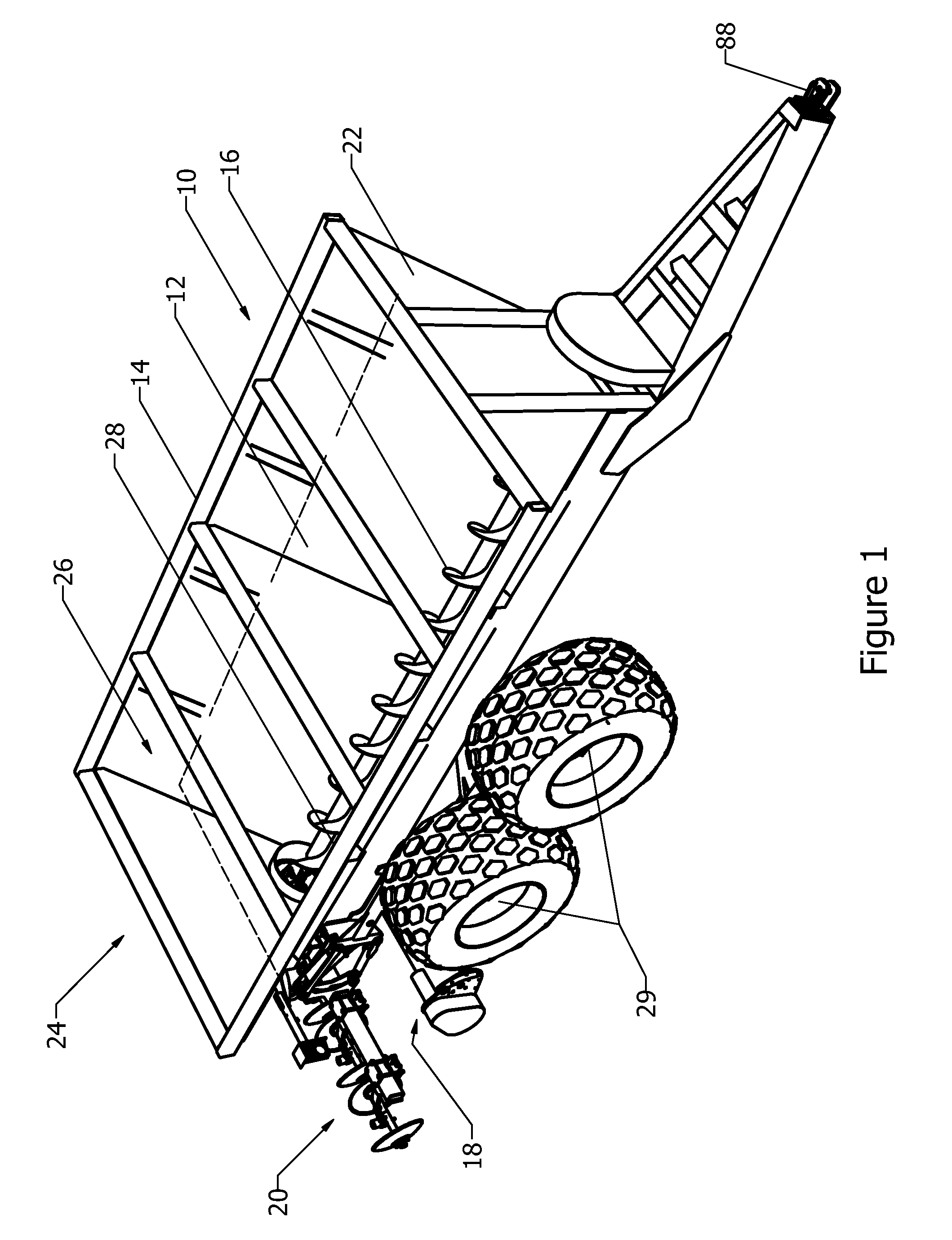
[0031]Reference is made to FIG. 1, which shows a vehicle 10 for handling semi-solid material, shown at 12, in accordance with an embodiment of the present invention. The semi-solid material 12 is shown as being transparent in FIG. 1 so as to reveal vehicle structure that would otherwise be hidden. The semi-solid material 12 may be any semi-solid material as previously described, for example bio-solids. Throughout the description, reference is made to bio-solids 12, however, this term may be used interchangeably to describe any suitable semi-solid material. The bio-solids 12 / semi-solid material 12 is shown in FIG. 1 and not in any of the other figures so as not to impinge on the clarity of those figures.

[0032]The vehicle 10 is used to apply the bio-solids 12 to land and may thus be referred to as a land application vehicle 10. The land application vehicle 10 includes a hopper 14, a longitudinal auger 16 positioned within the hopper 14, a distributor 18, and an optional incorporator 2...


PUM


Abstract

According to an aspect of the invention, there is provided a land application vehicle for a semi-solid material, such as bio-solids. The vehicle includes a hopper and a distributor. The distributor includes a housing having a distributor inlet and at least one distributor outlet, a first distributor auger in the housing configured for transferring semi-solid material away from the distributor inlet towards the at least one distributor outlet and a second distributor auger in the housing configured for transferring semi-solid material back towards the distributor inlet. This creates re-circulation of the semi-solid material within the distributor, which inhibits packing of the semi-solid material at the ends of the distributor and generally aids in uniform distribution of the material.

Description

CROSS REFERENCE TO RELATED APPLICATIONS[0001]This application claims the benefit of U.S. patent application 61 / 083,903, filed on Jul. 25, 2008, which is incorporated herein by reference.FIELD OF THE INVENTION[0002]The present invention relates to the application of semi-solid material to land, and more particularly to a vehicle for the application of bio-solids to farmland.BACKGROUND OF THE INVENTION[0003]In the treatment of wastewater, either from industrial, agricultural or municipal sources, bio-solids or sludge are produced. One of the main problems in wastewater treatment is the environmentally safe and economic disposal of sludge.[0004]One of the more favored methods of sludge disposal is by application onto agricultural land. In one such method, sludge is removed from a wastewater treatment plant in a highly liquid state and spread on to the land using a vehicle equipped with pumps that spray the sludge outward of the vehicle or, in some cases, inject the sludge into the soil...

Claims


Application Information

Patent Timeline
Patent Type & Authority Applications(United States)
IPC IPC(8): A01C3/06B65G65/00
CPCA01C3/066A01C3/04
Inventor NUHN, DENNIS
Owner NUHN INDS
Learn More