Release liner staging unit and system incorporating same

a technology of staging unit and release liner, which is applied in the direction of mechanical control devices, instruments, process and machine control, etc., can solve the problems of liner breaking, and achieve the effect of hysteresis and production of saturated levels

Active Publication Date: 2005-11-17
VALCO CINCINNATI
View PDF1 Cites 2 Cited by
  • Summary
  • Abstract
  • Description
  • Claims
  • Application Information

AI Technical Summary

Benefits of technology

[0012] Optionally, storing the selectively fed release liner includes storing it in a substantially serpentine pattern in the accumulator's storage compartment. In another option, a drive mechanism is operated to effect feeding of the release liner, where the drive mechanism includes a motor, one or more drive roller responsive to the motor such that they movably contact the release liner, and a brake cooperative with the motor. The brake and motor can work together such that when the motor is turning the drive roller, the brake is preferably disengaged, thereby not substantially inhibiting the movement of the release liner into the accumulator. Contrarily, when operation of the motor ceases, the brake engages the release liner to slow down or stop movement of the release liner into the accumul

Problems solved by technology

Upon dispensing of this upstream portion of the line

Method used


Image

  • Release liner staging unit and system incorporating same
  • Release liner staging unit and system incorporating same
  • Release liner staging unit and system incorporating same

Examples


Embodiment Construction

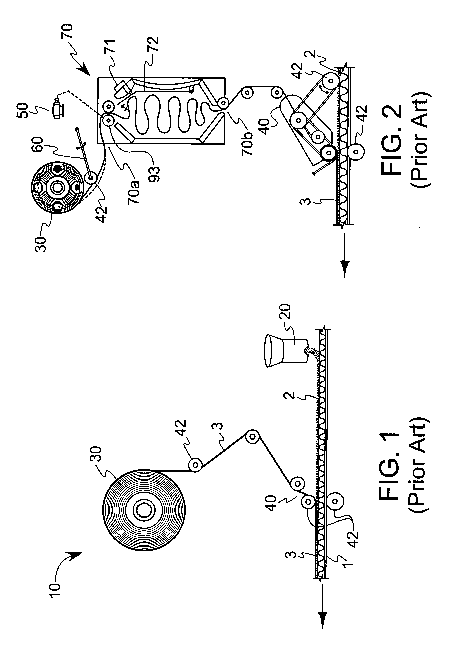
[0025] Referring first to FIG. 1, an adhesive layer and release liner application system 10 according to the prior art is shown. The system 10 sequentially places an adhesive layer 2 and a release liner 3 onto a moving substrate 1. In one configuration, the adhesive layer 2 is a hot melt adhesive that is deposited in viscous liquid form, while the release liner 3 is a relatively thin (on the order of a few mils or less) film of silicone coated paper or similar non-adherent material. The substrate is a generally planar paper, plastic or cardboard material which, after adhesive deposition, can be folded or stacked for subsequent use. The system 10 includes an adhesive application device 20, spool 30 of release liner and a release liner application device 40 with numerous rollers 42. Adhesive application device 20 typically includes a vat to store the adhesive, as well as related heating devices and conduit to liquefy and transport the adhesive to one or more deposition nozzles.

[0026]...


PUM

PropertyMeasurementUnit
Shapeaaaaaaaaaa
Widthaaaaaaaaaa
Hysteresisaaaaaaaaaa

Abstract

A release liner staging unit for depositing a release liner onto an adhesive layer. The unit includes an accumulator that creates a buffer between an amount of release liner supplied and an amount needed for covering a layer of adhesive. The tendency of release liner placed within the accumulator to settle allows additional release liner to be introduced, thereby producing a slightly saturated level of release liner in the accumulator. Time delays can be accounted for to reduce the number of times a drive mechanism needs to operate, thereby reducing wear on such componentry. The unit may also form part of a larger release liner application device and adhesive application system.

Description

CROSS-REFERENCE TO RELATED APPLICATIONS [0001] This application is based on U.S. provisional application Ser. No. 60 / 565,646, filed Apr. 27, 2004.BACKGROUND OF THE INVENTION [0002] This invention relates generally to a device for applying a release liner to an adhesive that is disposed on a substrate, and more particularly to an improved accumulator that regulates the tension in the release liner as the liner is being applied. [0003] Automated gluing systems are routinely used to affect high-speed, repeatable application of adhesives to various substrates such that upon contact between the adhesive-containing substrate and another surface, a bond or seal is formed. Such systems are employed in deferred-use packaging, where a pressure-sensitive adhesive is covered with a release liner such that upon subsequent removal of the release liner and placement of the exposed adhesive in contact with a desired surface, the surface on which the adhesive is placed and the desired surface can be...

Claims


Application Information

Patent Timeline
IPC IPC(8): B32B37/20B32B38/18B65H26/00
CPCB32B37/1284B32B38/18B32B37/20
Inventor MAINOUS, DAVID LEEPOPHAM, DAVID ALLENCHAMBERS, JOHN PAUL G.JAMISON, CHRIS MARK
Owner VALCO CINCINNATI
Why Eureka
Try Eureka