
Protective covers for phylacteries

a protective cover and phylacterie technology, applied in the field of protective covers for phylacteries, can solve the problems of insufficient ledge formed by the protective cover to adequately support the entire knot, inability to securely wrap around the sides of the protective cover, and long strap b>22/b>

Inactive Publication Date: 2012-01-05
ADLER IRA N
View PDF2 Cites 2 Cited by
  • Summary
  • Abstract
  • Description
  • Claims
  • Application Information

AI Technical Summary

Benefits of technology

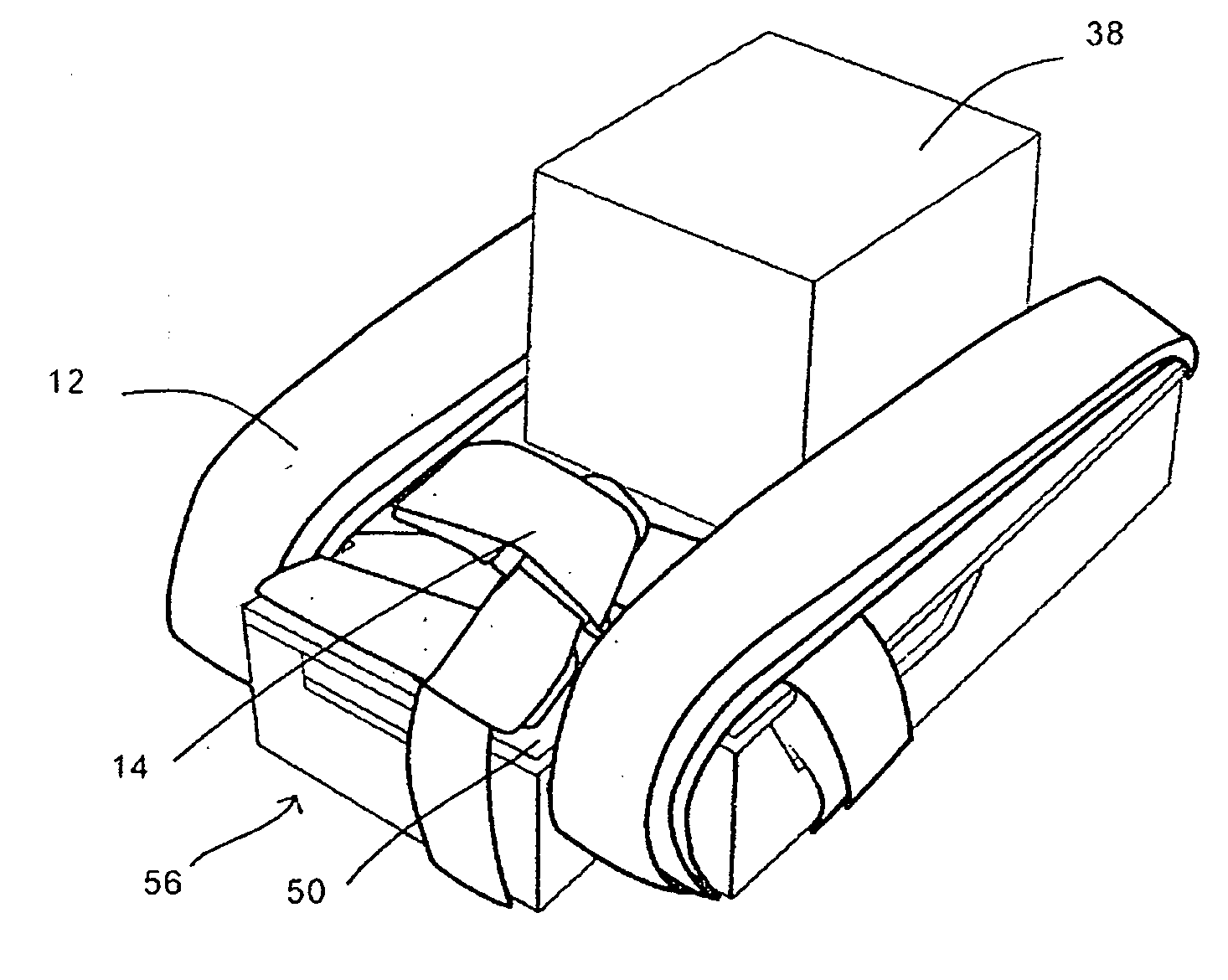
[0016]The protective cover in accordance with the invention includes a supplemental platform or support surface arranged alongside a rear side of the cube-shaped portion which faces the slot of the protective cover. The supplemental support surface is formed to enable the knot of the strap of the head Phylactery to be seated comfortably and securely thereon when the head Phylactery is housed in the protective cover and to substantially preclude the possibility of wrapping hanging portions of the strap around the knot when supported on the supplemental support surface. To this end, the supplemental support surface should extend only alongside a rear surface of the cube-shaped portion and thus not entirely across a rear side of the protective cover. An indentation or step is thereby formed alongside each lateral side of the protective cover and the hanging portions of the strap of the head Phylactery are wrapped through these indentations and not over the supplemental support surface on which the knot is seated.

Problems solved by technology

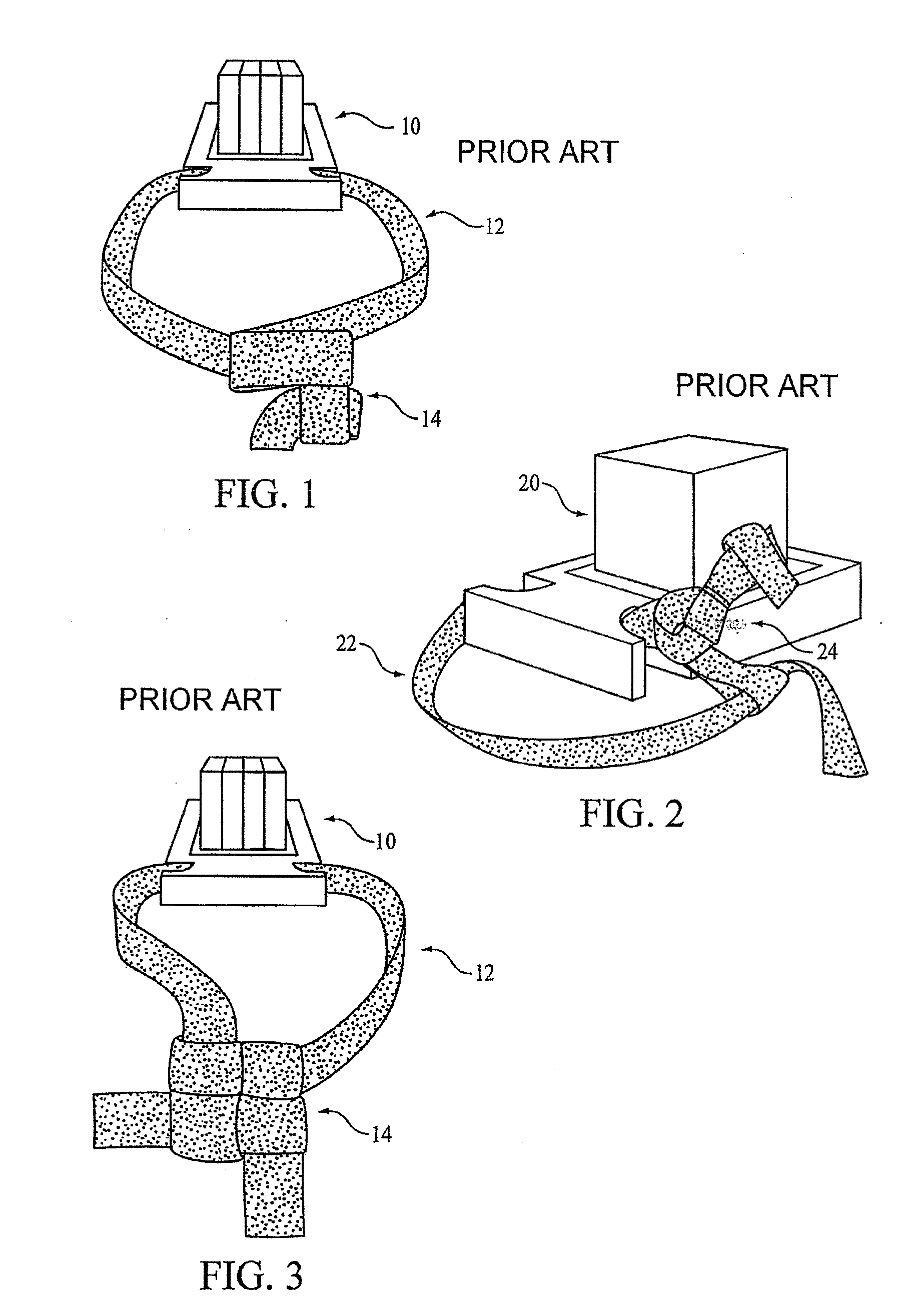
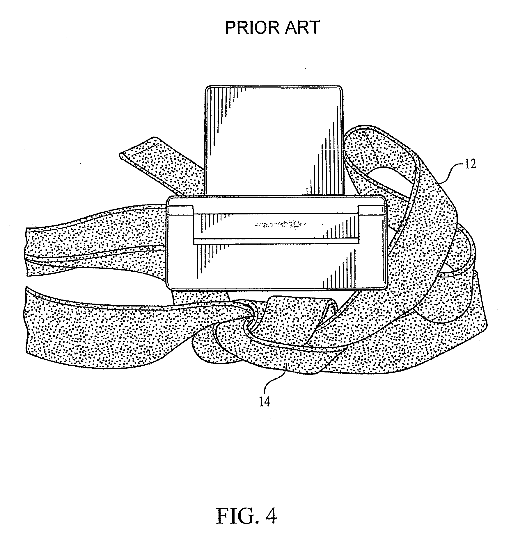
Moreover, in conventional protective covers, there is an insufficient ledge formed by the protective cover to adequately support the entire knot 14.
However, sometimes, the strap 22 is quite long and cannot be securely wrapped around the sides of the protective cover without covering a portion of the knot 24.

Method used


Image

  • Protective covers for phylacteries
  • Protective covers for phylacteries
  • Protective covers for phylacteries

Examples


Embodiment Construction

[0033]Referring to the accompanying drawings wherein the same reference numerals refer to the same or similar elements, FIGS. 5-11 which show a protective cover intended for primary use for a head Phylactery which is designated generally as 30. Each protective cover 30 comprises an upper shell member 34 and a lower shell member 36 which in combination, define a hollow interior contoured to fit the head Phylactery. The box 10 of the head Phylactery fits inside this hollow interior and therefore the upper shell member 34 includes a generally cube-shaped portion 38, i.e., it has the same shape as the Phylactery box 10. The upper shell member 34 also includes a substantially planar lower surface 40 which surrounds the cube-shaped portion 38. This lower surface 40 is not rectangular as is the surface 80 in the conventional protective cover 62 shown in FIGS. 4A-4D, but rather has a unique shape that is designed to enable placement of the knot of the strap 14 of the head Phylactery thereon...


PUM


Abstract

Protective covers for Phylacteries including an upper shell member and a lower shell member at least partially separable from one another and which, when together, define a hollow interior contoured to fit the Phylactery. One or two lateral extension portions, depending on whether the protective cover is for a head Phylactery or an arm Phylactery, are situated partly on each of the upper and lower shell members outward from a respective plane including a side surface of the cube-shaped portion and have a width of at least about 1.2 centimeters. A supplemental platform or support surface may be arranged alongside a rear side of a cube-shaped portion of the upper shell member facing the slot of the protective cover to support for a knot of the strap of the head Phylactery when the head Phylactery is housed in the protective cover.

Description

CROSS REFERENCE TO RELATED APPLICATION[0001]This application is a continuation-in-part of U.S. patent application Ser. No. 12 / 140,298 filed Jan. 7, 2008, incorporated by reference herein.FIELD OF THE INVENTION[0002]The present invention is directed to protective covers for Phylacteries that allows for the placement of straps attached to the Phylacteries box to be more easily stored in conformity with Jewish law and code.BACKGROUND OF THE INVENTION[0003]For Jewish men, there is a Biblical obligation to wear a set of Phylacteries (also called tefillin), generally during the morning prayer service. A set of Phylacteries comprises a head unit for placement on the head and an arm unit for placement on the arm. Each Phylactery comprises two major components: a leather box that contains specific portions of the Bible written on parchment and a leather strap (retsua) attached to the box.[0004]While initially preparing the straps and allowing for proper use, the leather straps are tied to he...

Claims


Application Information

Patent Timeline
IPC IPC(8): B65D85/00
CPCA47G33/00
Inventor ADLER, IRA N.
Owner ADLER IRA N
Learn More