Motor manufacturing method

a manufacturing method and motor technology, applied in the direction of magnetic circuit rotating parts, magnetic circuit shape/form/construction, instruments, etc., can solve the problem that the motor cannot perform the operation in a stable manner, and achieve the effect of minimizing deviations from the designed dimensions

Inactive Publication Date: 2010-01-28
SAMSUNG ELECTRO MECHANICS CO LTD
View PDF5 Cites 0 Cited by
  • Summary
  • Abstract
  • Description
  • Claims
  • Application Information

AI Technical Summary

Benefits of technology

[0008]An aspect of the claimed invention is to provide a motor having high precision with less deviation from the designed dimensions, using a base cover made of an elastically deformable material that can be made to touch the shaft by pressing.
[0009]Also, an aspect of the claimed invention is to provide a method of manufacturing a motor with which deviations from the designed dimensions can be minimized, by coupling a hub onto a shaft by pressing such that the shaft is inserted, while supporting a base cover in the axial direction of the shaft.

Problems solved by technology

However, if the hub is pressed with a load relatively less than that which causes mechanical damage, a sufficient load may not be applied, and as the gaps between components, etc., deviate further from the designed dimensions, problems may occur as the motor cannot perform operations in a stable manner.

Method used


Image

  • Motor manufacturing method
  • Motor manufacturing method
  • Motor manufacturing method

Examples


Embodiment Construction

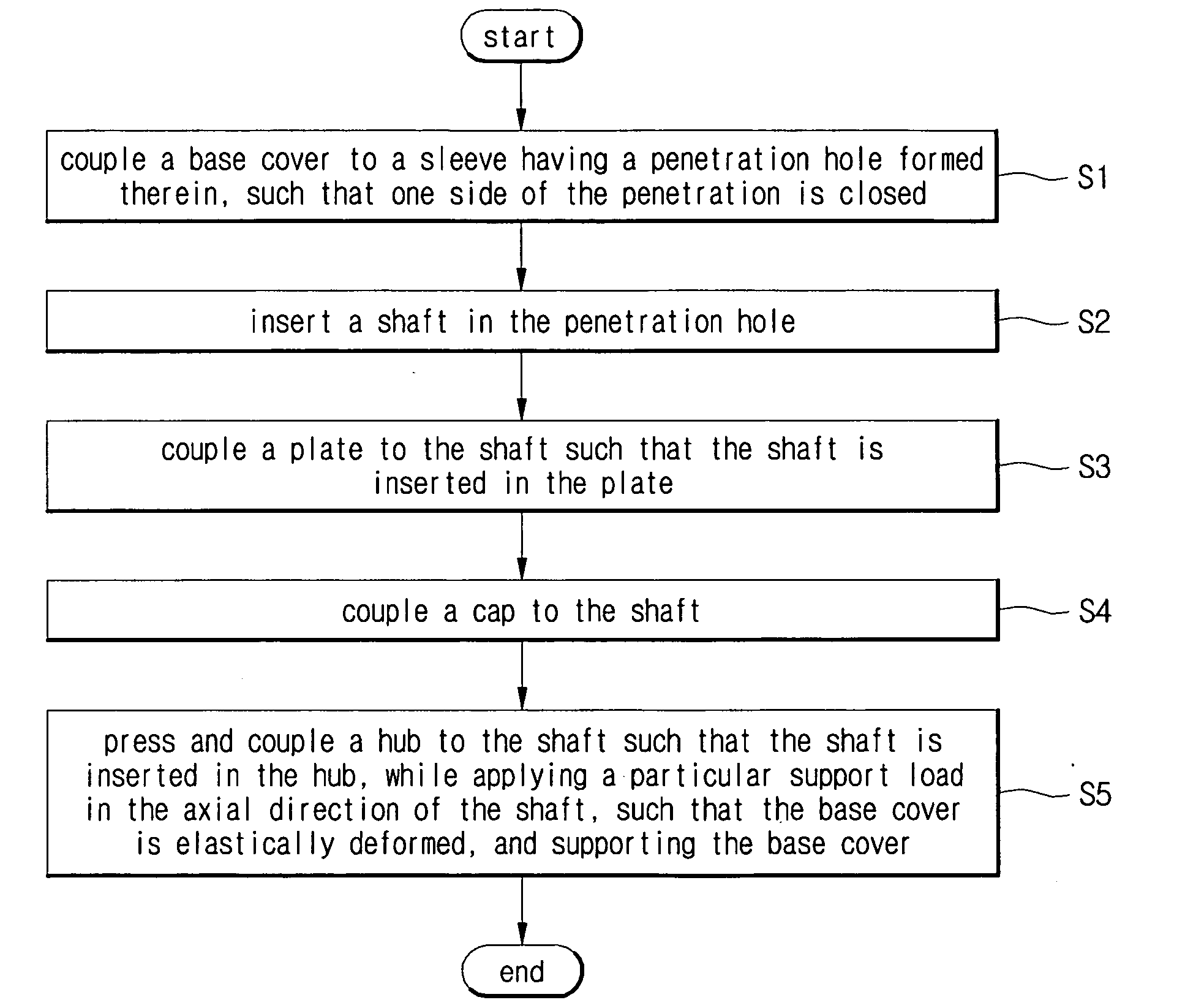
[0028]The motor and manufacturing method thereof according to certain embodiments of the invention will be described below in more detail with reference to the accompanying drawings, in which those components are rendered the same reference number that are the same or are in correspondence, regardless of the figure number, and redundant explanations are omitted.

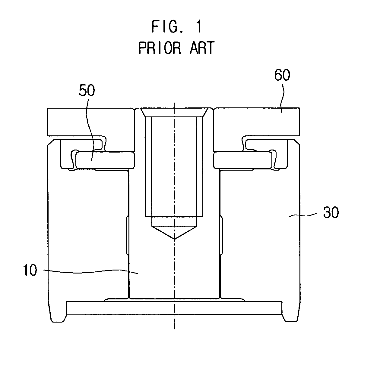
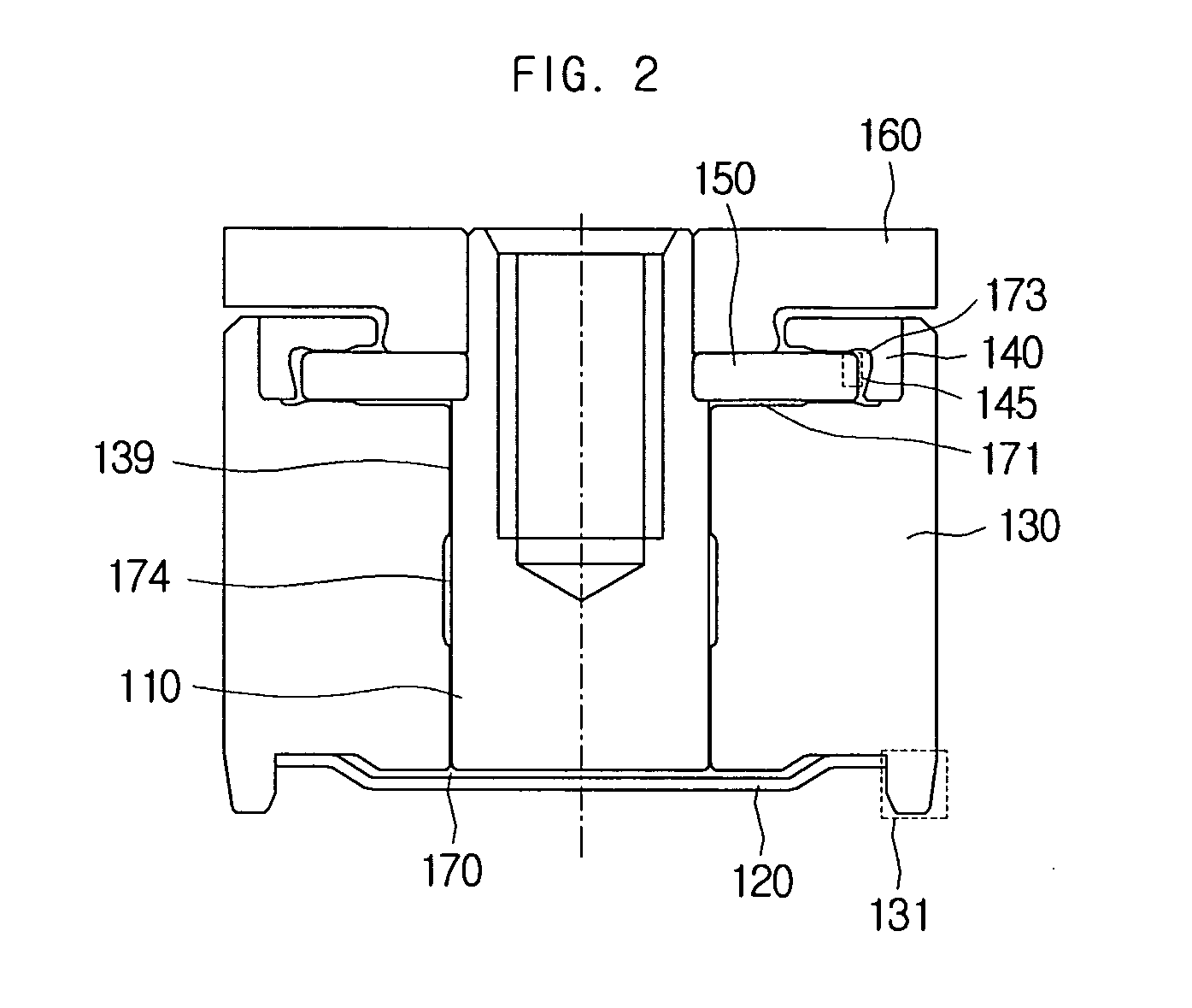
[0029]In general, a motor consists basically of a rotating member, a stationary member that supports the rotating motion of the rotating member, and a bearing placed between the rotating member and the stationary member. For example, the rotating member may be a coupled body including a shaft, a hub coupled to and rotating together with the shaft, and a plate, etc., and the stationary member may be a sleeve, etc., surrounding the shaft.

[0030]However, the rotating member and the stationary member are not determined by the components per se, but are determined by their designed functions. That is, there may be cases where the s...


PUM

PropertyMeasurementUnit
perimeteraaaaaaaaaa
forceaaaaaaaaaa
shapeaaaaaaaaaa

Abstract

A method of manufacturing a motor includes coupling a base cover to a sleeve having a penetration hole formed therein, such that one side of the penetration hole is closed; inserting a shaft in the penetration hole; coupling a plate to the shaft such that the shaft is inserted in the plate; and pressing and coupling a hub to the shaft such that the shaft is inserted in the hub while the base cover is supported in an axial direction of the shaft.

Description

CROSS-REFERENCE TO RELATED APPLICATIONS[0001]This application is a divisional and claims priority to U.S. application Ser. No. 11 / 882,588, filed Aug. 2, 2007, which in turn claims the benefit of Korean Patent Application No. 10-2006-0074555 filed with the Korean Intellectual Property Office on Aug. 8, 2006, the disclosures of which are incorporated herein by reference in their entirety.BACKGROUND[0002]1. Field[0003]The claimed invention relates to a motor manufacturing method.[0004]2. Description of the Related Art[0005]In general, a motor, especially a spindle motor, is used to operate the rotating polygonal mirror of a laser printer or the disk of a hard disk drive, etc. That is, various rotational bodies may be fixed as necessary to the outer perimeter of the hub. For example, in the case of an LSU (laser scanning unit), a rotating polygonal mirror may be installed, while in the case of a hard disk drive, a disk may be installed.[0006]FIG. 1 is a cross-sectional view illustrating...

Claims


Application Information

Patent Timeline
Patent Type & Authority Applications(United States)
IPC IPC(8): H02K15/00
CPCH02K1/28H02K15/02Y10T29/49025Y10T29/49009Y10T29/49639H02K15/16H02K15/14
Inventor LEE, TA-KYOUNGKIM, DUCK-YOUNG
Owner SAMSUNG ELECTRO MECHANICS CO LTD
Why Eureka
Try Eureka