
Method of producing unsaturated acid in fixed-bed catalytic partial oxidation reactor with high efficiency

a technology of unsaturated acid and catalytic partial oxidation, which is applied in the preparation of carbonyl compounds, organic chemistry, carboxylic compound preparations, etc., can solve the problems of increased production, reduced yield of (meth)acrylic acid, and difficulty in controlling the resultant reaction temperature, so as to suppress side reactions, reduce the magnitude of peak temperature in the first shell space, and inhibit heat accumulation

Inactive Publication Date: 2010-01-21
LG CHEM LTD
View PDF12 Cites 7 Cited by
  • Summary
  • Abstract
  • Description
  • Claims
  • Application Information

AI Technical Summary

Benefits of technology

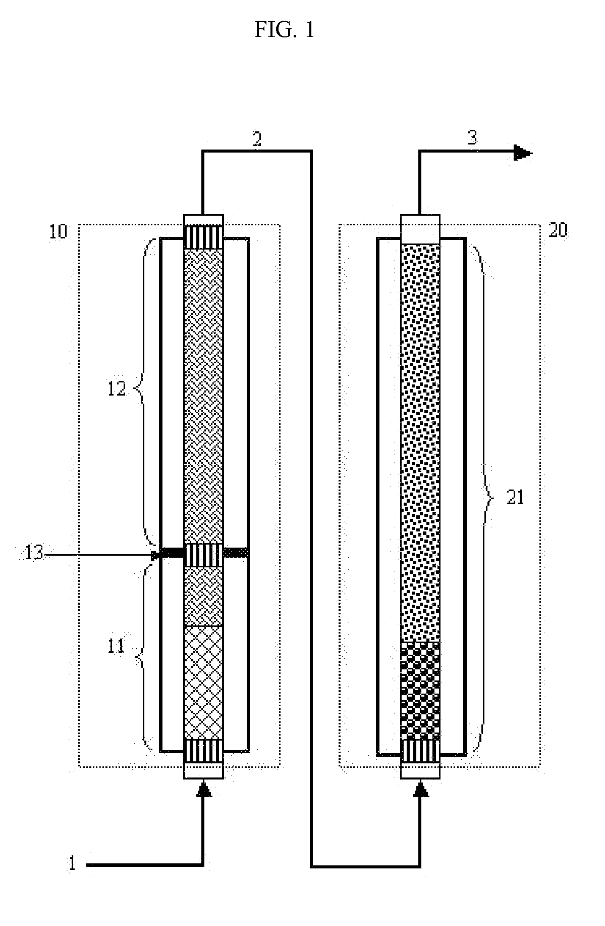
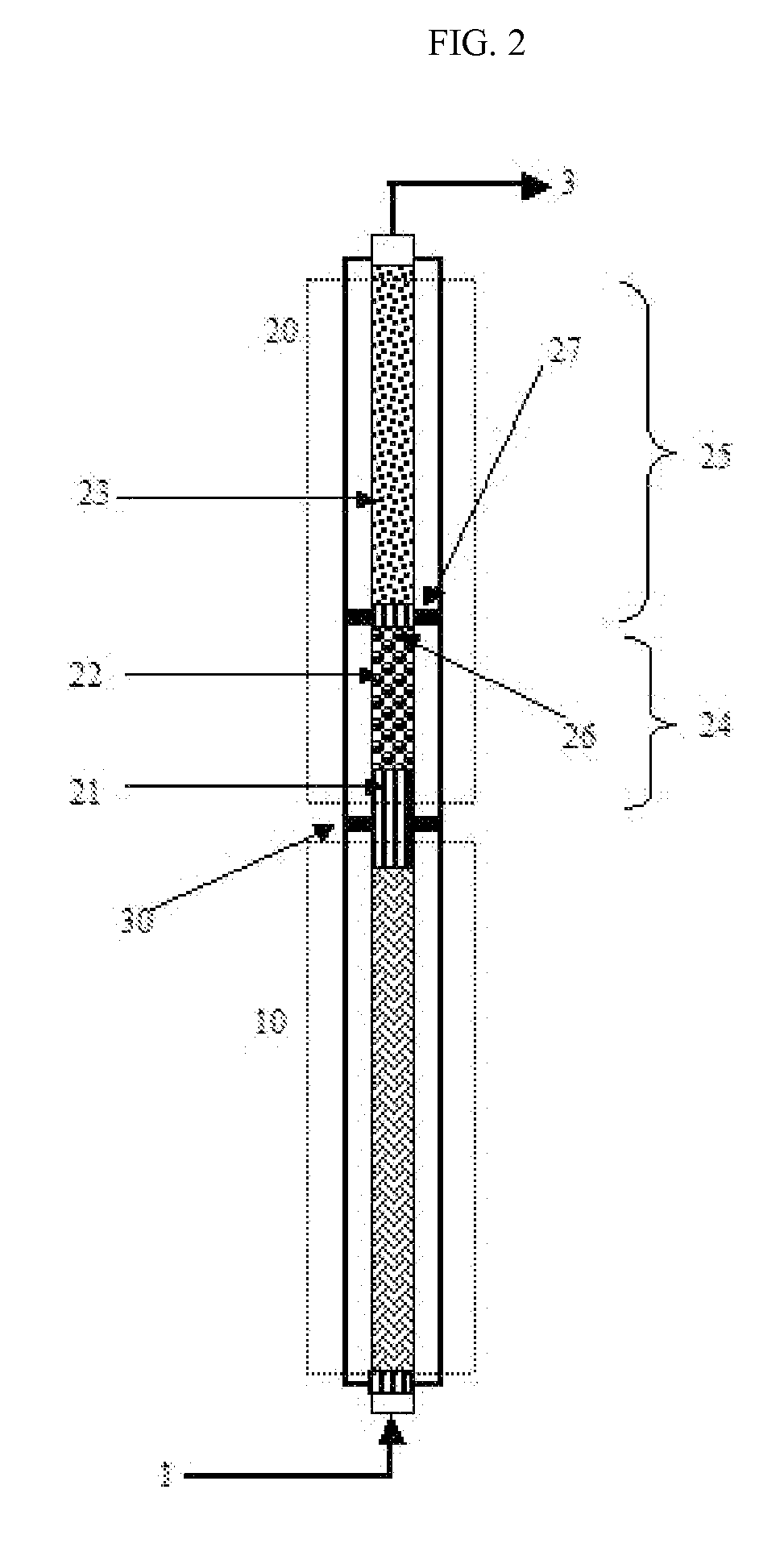
[0028]Additionally, when each reaction zone is divided into two or more shell spaces by using at least one partition and is subjected to heat control, it is possible to provide the process with high flexibility under the variations in temperature profile characteristics.
[0043]Therefore, in order to solve the aforementioned problem caused by the first shell space of each step, the temperature of the heat transfer medium in the first shell space of each step is decreased possibly to the lowest active temperature of the catalyst, according to the present invention. By doing so, it is possible to control the magnitude of a hot spot and to prevent heat accumulation in the vicinity of the hot spot, while not degrading reactivity severely.
[0055]Particularly, the temperature of the heat transfer media can be varied in the axial direction according to the present invention. Thus, it is possible to inhibit the catalyst from being damaged by an excessively high exothermic reaction and to prevent degradation in yield of the target product, resulting in improvement of the yield.
[0063]In the first shell space, the concentration and pressure of reactants are high, so that the temperature difference between the highest peak temperature of the catalyst layer and the temperature of the heat transfer medium is higher than that in the next shell space. For this reason, the temperature difference range in the first shell space will be surely wider than those in the next shell spaces. However, the present invention provides a method by which the magnitude of peak temperature in the first shell space is minimized while a temperature difference in the next shell space is limited in an extended range, thereby forming an overall temperature profile having a smooth shape.
[0064]According to the present invention, the temperature difference between the highest peak temperature of a catalyst layer in each reaction zone and the temperature of a heat transfer medium is controlled as described above, so that the catalyst can show uniform activity in the axial direction. Thus, it is possible to inhibit heat accumulation in a hot spot and suppress side reactions, thereby preventing a drop in yield.
[0068]Preferably, a layer formed of an inactive material or a mixture of an inactive material and a catalytic material, i.e., a reaction inhibition layer, is disposed within a portion of the catalytic tube, which corresponds to a position where the partition is disposed. By doing so, it is possible to eliminate a problem in heat transfer at the position where the partition is disposed.

Problems solved by technology

However, in this case, rapid oxidation occurs in the reactor, which makes it difficult to control the resultant reaction temperature.
Also, a hot spot is generated in the catalyst layer of the reactor, and heat accumulation occurs in the vicinity of the hot spot, resulting in increased production of byproducts, such as carbon monoxide, carbon dioxide and acetic acid at high temperature, and in a drop in yield of (meth)acrylic acid.
Furthermore, production of (meth)acrylic acid using high space velocity and high concentration of propylene or the like causes various problems, as the reaction temperature abnormally increases in the reactor, such problems including the loss of active ingredients from the catalyst layer, a drop in the number of active sites caused by sintering of metal components, or the like.
Consequently, this leads to deterioration of the function of the catalyst layer.

Method used


Image

  • Method of producing unsaturated acid in fixed-bed catalytic partial oxidation reactor with high efficiency
  • Method of producing unsaturated acid in fixed-bed catalytic partial oxidation reactor with high efficiency

Examples


reference example 1

Determination of Lowest Active Temperature of Catalyst Layer Corresponding to First Shell Space of First Step

[0077]A pilot reactor in which the first step is conducted in one catalytic tube was provided. The catalytic tube had an inner diameter of 26 mm. In the first-step catalytic tube, a catalyst layer was packed to a height of about 1200 mm. At this time, two kinds of catalysts having activity increasing along the axial direction from the inlet to the outlet were packed to a height of 320 mm and 880 mm, respectively (see “Method of Controlling Catalytic Activity” described in U.S. Pat. No. 3,801,634 and U.S. Pat. No. 4,837,360). The catalyst was comprised of the first-step oxidation catalyst material obtained according to the method as disclosed in Korean Patent Publication No. 0349602 (Korean Patent Application No. 10-1997-0045132), the catalyst material being based on molybdenum (Mo) and bismuth (Bi).

[0078]The first catalyst layer (referred to as LGC1 hereinafter) of the first-...

example 1

Variations in Yield and in Magnitudes of Temperature Peaks at Hot Spots Depending on Variations in Temperature Setting of Molten Salt

[0086]As shown in FIG. 1, a pilot reactor was provided in which each of first-step reaction and second-step reaction is conducted in one catalytic tube (included in zone 10 or 20 of FIG. 3). The catalytic tube had an inner diameter of 26 mm, and the first-step catalytic tube was filled with catalyst layers to a height of about 1200 mm, and the second-step catalytic tube was filled with catalyst layers to a height of about 1100 mm.

[0087]In the catalyst layers of the first step reaction zone 10, two kinds of catalysts having activity increasing along the axial direction from the inlet to the outlet were packed to a height of 320 mm and 880 mm, respectively (see “Method of Controlling Catalytic Activity” described in U.S. Pat. No. 3,801,634 and U.S. Pat. No. 4,837,360). In the catalyst layers of the second-step reaction zone 20, two kinds of catalysts hav...

example 2

Variations in Yield and in Magnitudes of Temperature Peaks at Hot Spots Depending on Variations in Temperature Setting of Molten Salt

[0097]This example was performed in the same manner as described in Example 1, except that the temperatures of the molten salt in the first-step reaction zone (first-step reactor) were set to 300° C. and 315° C., respectively, in an axial direction. In the first shell space of the first step, the value defined by Equation 1 was about 1.9.

[0098]In the zone corresponding to the first shell space in the first-step reaction zone, a hot spot with a temperature of 381.2° C. was generated. The yields of acrolein and acrylic acid were 79.02% and 11.46%, respectively. In the second-step reaction zone operated under isothermal conditions, the temperature of a hot spot was 327.5° C., and the yields of acrolein and acrylic acid were 0.607% and 84.95%, respectively.


PUM

PropertyMeasurementUnit
active temperatureaaaaaaaaaa
temperatureaaaaaaaaaa

Abstract

A shell-and-tube heat exchanger-type reactor including one or more catalytic tubes, each including a first-step reaction zone and a second-step reaction zone, wherein at least one of the first-step reaction zone and the second-step reaction zone is divided into two or more shell spaces by a partition; each of the divided shell spaces is independently heat-controlled; and a heat transfer medium having a temperature from the lowest active temperature of a catalyst layer in a reaction tube corresponding to the first shell space of the first-step reaction zone or the first shell space of the second-step reaction zone to the lowest active temperature of the catalyst layer plus 20° C.; and the first shell space of the first-step reaction zone or the first shell space of the second-step reaction zone is controlled so as to provide a reactant conversion contribution per length of 1.2˜2.5.

Description

[0001]This application is a divisional of U.S. application Ser. No. 11 / 483,752, filed Jul. 10, 2006, which claims the benefit of the filing date of Korean Patent Application No. 2005-61797, filed on Jul. 8, 2005, in the Korean Intellectual Property Office. The disclosure of both applications is incorporated herein in their entirety by reference.TECHNICAL FIELD[0002]The present invention relates to a process for producing unsaturated aldehydes and / or unsaturated acids from olefins or alkanes in a fixed bed shell-and-tube heat exchanger-type reactor by catalytic vapor phase oxidation, as well as a heat exchanger-type reactor for use in the same process.BACKGROUND ART[0003]A process for producing unsaturated aldehydes and / or unsaturated acids from olefins or alkanes in vapor phase by using a catalyst is a typical process of catalytic vapor phase oxidation.[0004]Particular examples of such catalytic vapor phase oxidation include a process for producing acrolein and / or acrylic acid by th...

Claims


Application Information

Patent Timeline
Patent Type & Authority Applications(United States)
IPC IPC(8): B01J8/04
CPCB01J8/0453B01J8/0457C07C51/252C07C51/215C07C45/37C07C45/36C07C45/35C07C45/34B01J2219/0004B01J2208/025B01J2208/0053B01J2208/00212B01J8/067C07C47/21C07C47/22C07C57/04
Inventor HA, KYOUNG SUWOO, BOO GONKO, JUN SEOKKANG, SEONG PILCHOI, SEOK HWANKIM, YOUNG BAE
Owner LG CHEM LTD
Learn More