
Downhole cables with both fiber and copper elements

a hybrid cable and downhole technology, applied in the direction of insulated conductors, cables, instruments, etc., can solve the problems of cable designer's work, excessive fiber length (efl) in the tube must be relatively low, and copper wire b>6/b> is not easily segregated from stainless steel tubes, etc., to achieve the effect of increasing the strain free window of downhole cable and not excessive straining optical fibers

Active Publication Date: 2010-01-14
AFL COMM LLC
View PDF25 Cites 68 Cited by
  • Summary
  • Abstract
  • Description
  • Claims
  • Application Information

AI Technical Summary

Benefits of technology

[0012]The present invention provides a downhole cable that increases a strain free window of the downhole cable.
[0013]The present invention also provides a downhole cable which can be elongated by tension or temperature, without excessively straining an optical fiber within an element in the downhole cable.

Problems solved by technology

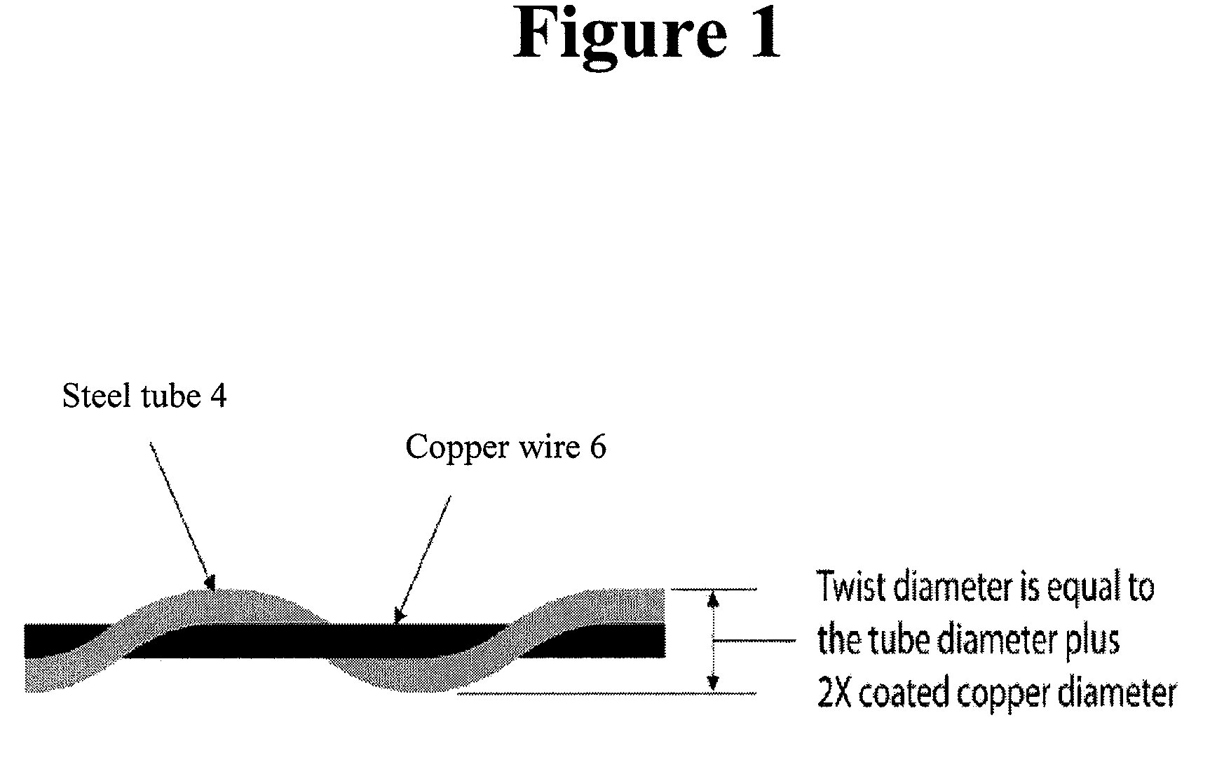
The disadvantage of item (1) is that the copper wire 6 is not easily segregated from the stainless steel tube.
Another disadvantage is that the center stainless steel tube has to be of such a size that the excess fiber length (EFL) in the tube must be relatively low, in the case where a multi-mode optical fiber is deployed in it.
This can be an issue for environments where the cable temperature will be elevated.
This results in the cable designer needing to work in a small space to house the desired copper and fiber elements.
In order to fit a 0.080 inch fiber filled stainless steel tube into this ¼″ tube and to include copper elements with the appropriate insulation level to ensure proper performance of the copper, the size of the stainless steel tube is limited.
Increased strain reduces fiber life, can increase attenuation (optical loss), and can affect other attributes on the fiber.
This is a drawback to this type of design since the center stainless steel tube size limits the EFL in the tube.
However, due to the size of the plastic tubes, the amount of benefit is limited.
However, with this structure, the disadvantage is that the inherent strength of the structure is limited because the strength element of the structure is only the center copper wire.
This becomes problematic as processing tensions on the core and installation practices can result in high tension levels on the cable, thus exposing the fiber to strain.
Another disadvantage of item (2) is its crush resistance.

Method used


Image

  • Downhole cables with both fiber and copper elements
  • Downhole cables with both fiber and copper elements
  • Downhole cables with both fiber and copper elements

Examples


Embodiment Construction

[0031]Certain exemplary embodiments of the present invention will now be described in greater detail with reference to the accompanying drawings.

[0032]In the following description, same drawing reference numerals are used for the same elements even in different drawings. The matters defined in the description, such as detailed construction and elements, are provided to assist in a comprehensive understanding of the invention. Thus, it is apparent that the present invention can be carried out without those specifically defined matters. Also, well-known functions or constructions are not described in detail since they would obscure the invention with unnecessary detail.

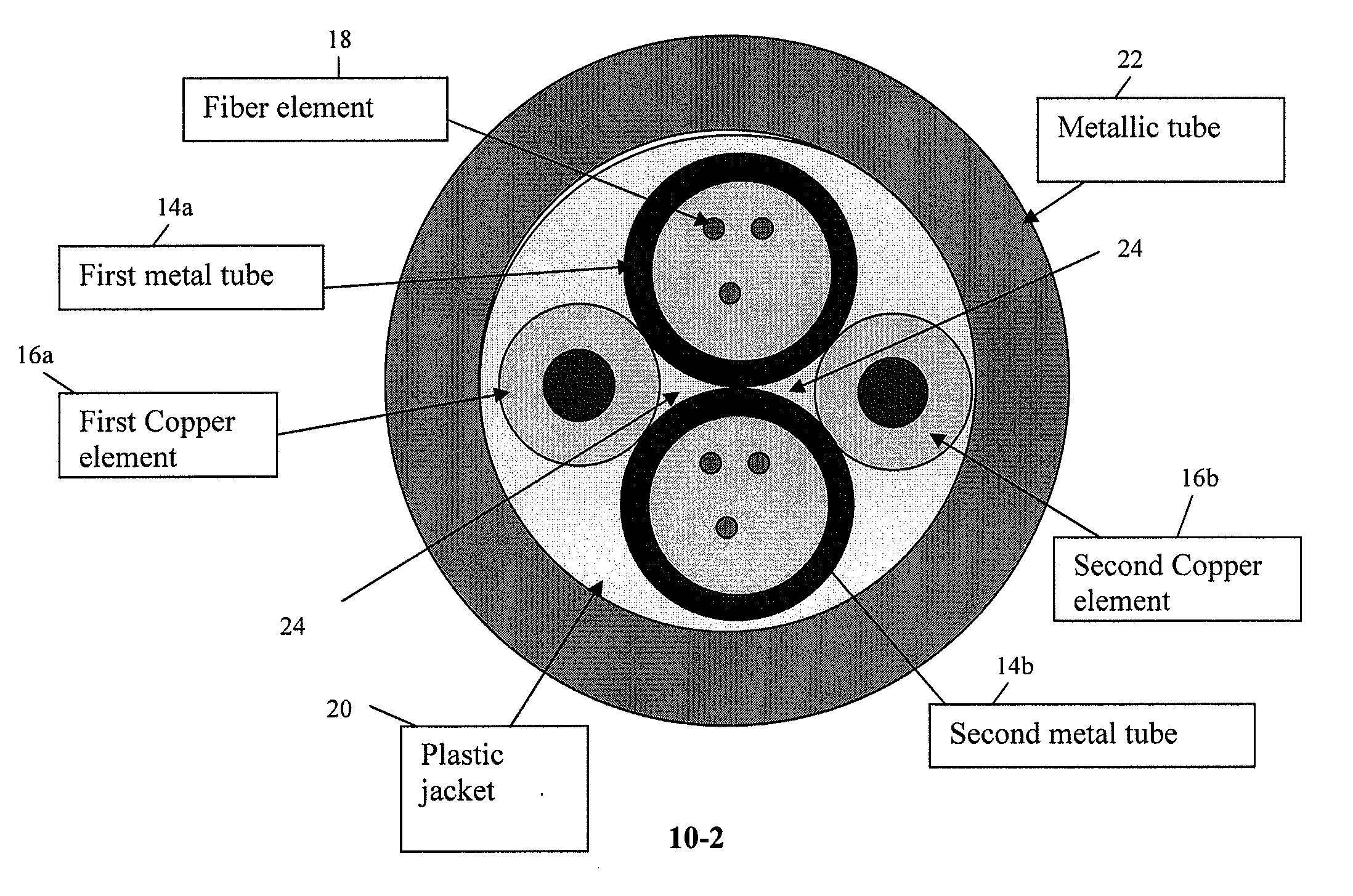
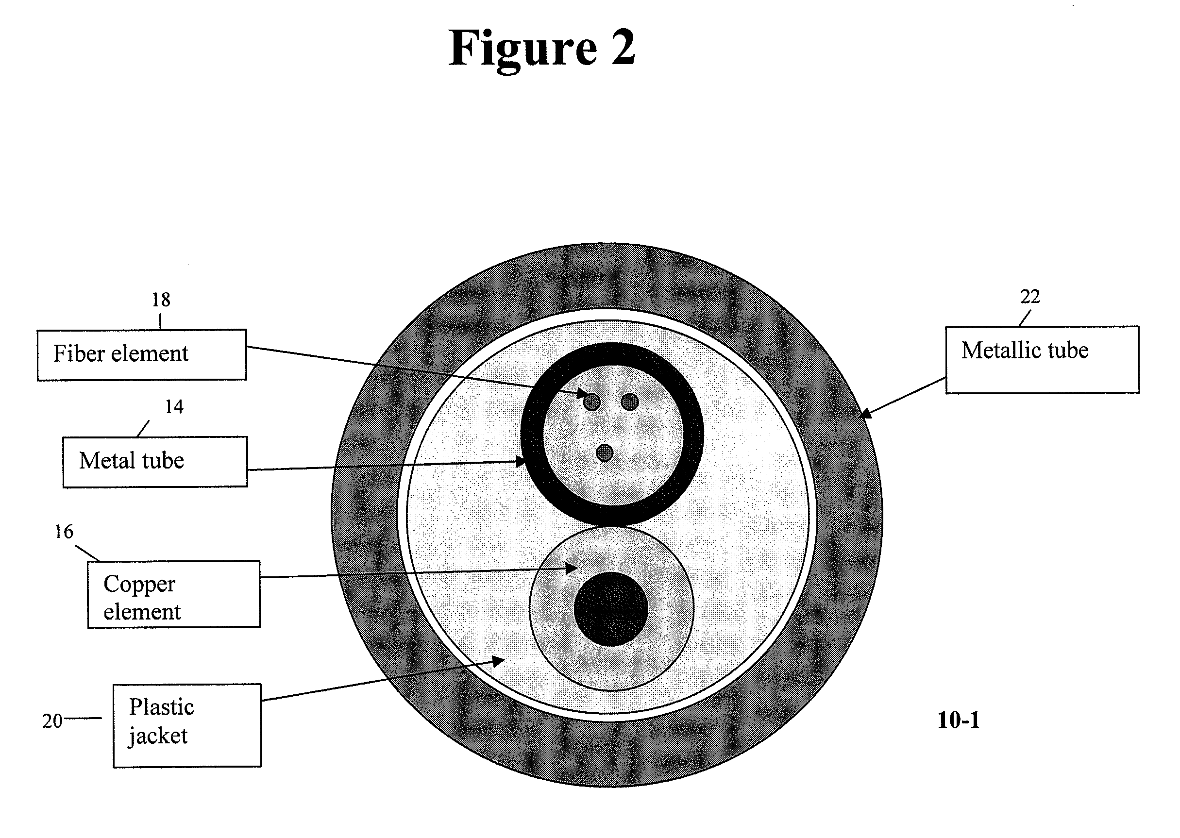
[0033]A down hole cable according to an exemplary embodiment of the present invention, and a method of manufacturing the down hole cable of this exemplary embodiment, will be described with reference to FIG. 2 and FIG. 3. FIG. 2 shows a cross-section of a down hole cable according the first exemplary embodiment of the p...


PUM

PropertyMeasurementUnit
Shapeaaaaaaaaaa
Areaaaaaaaaaaa

Abstract

Provided is a method of manufacturing a downhole cable, the method including, forming a helical shape in an outer circumferential surface of a metal tube, the metal tube having a fiber element housed therein, and stranding a copper element in a helical space formed by the metallic tube. Also provided is a downhole cable including, a metallic tube having a helical space in an outer circumferential surface thereof, wherein the metallic tube has a fiber element housed therein, and a copper element disposed in a helical space formed by the steel tube. Double-tube and multi-tube configurations of the downhole cable are also provided.

Description

CROSS-REFERENCE TO RELATED APPLICATIONS[0001]This application claims priority from U.S. Provisional Application No. 60 / 823959, filed on Aug. 30, 2006, the disclosure of which is incorporated herein by reference in its entirety.BACKGROUND OF THE INVENTION[0002]1. Field of the Invention[0003]Apparatuses and methods consistent with the present invention relate to a downhole hybrid cable, and more particularly to a downhole hybrid cable that has both fiber and copper elements.[0004]2. Description of the Related Art[0005]Hybrid cables with fiber and a copper wire are used for various purposes. For example, they are used for supplying power via the copper wire while sensing is carried out on the fiber. Also, sensing can be carried out via the copper wire as well. Such hybrid cables have also been employed in logging cables for downhole use. The logging cables are meant to be put into, for instance, an oil well to collect sample measurements of the well structure. After completion of the m...

Claims


Application Information

Patent Timeline
IPC IPC(8): G02B6/44H01R43/00
CPCG02B6/4416G02B6/4488G02B6/449Y10T29/49117H01B13/02Y10T29/49194H01B7/046H01B1/026G02B6/032G02B6/4479G02B2006/0325H01B11/22G02B6/443
Inventor HERBST, BRIAN
Owner AFL COMM LLC
Learn More