
Laser target seeker device

Active Publication Date: 2010-01-07
SAAB AB
View PDF4 Cites 9 Cited by
  • Summary
  • Abstract
  • Description
  • Claims
  • Application Information

AI Technical Summary

Benefits of technology

[0008]One object of the present invention is to provide a laser target seeker with improved accuracy.
[0009]Another object of the present invention is to provide a flyable body, for example a missile, for striking a target by means of a reflected laser beam with improved accuracy.
[0010]A further object of the present invention is to provide a system for striking a target by means of a reflected laser beam with improved accuracy.

Problems solved by technology

A problem with the quadrant detector is that the accuracy is quite low, which might lead to the missile or the like missing the target.
Then the centre point may be found with higher accuracy but when the reflex is located outside the centre it is not possible to determine how far from the centre it is.
There are however some limitations in using a two dimensional matrix having more than four elements.
The amplifiers connected to the wires drawn from the inner elements need to be placed further away, leading to a higher capacitance, which increases the noise and consequently affects the accuracy.

Method used


Image

  • Laser target seeker device
  • Laser target seeker device
  • Laser target seeker device

Examples


first embodiment

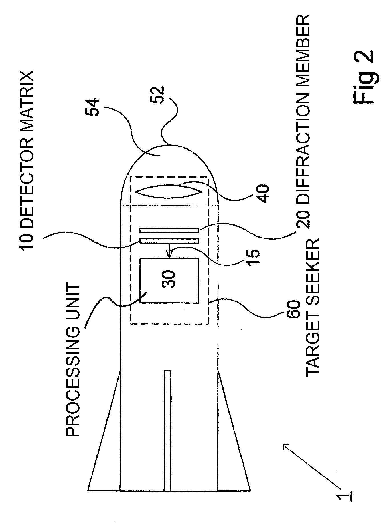
[0052]An advantage offered by the laser target seeker according to the present invention is that the detector elements 12 of the detector matrix may be of a smaller size than of a conventional detector matrix where the detector elements 12 constitute the detector matrix 10, connected to each other in the same plane, the edges of the elements facing each other. The fact that the detector elements are smaller, i.e. the surface of each detector element only covers a portion of each field of the matrix, facilitates mounting the detector elements on a separate support plate 18 which could be of a cheaper material than the detector elements, and thus material cost would be reduced due to reduced amount of semiconductor material. Another advantage, which is a consequence of the smaller detectors, is that the fill factor is reduced due to the fact that, there is space on the surface of the support plate not covered by the detector elements, where the wires from each detector element may be ...

second embodiment

[0056]In FIG. 3 the laser target seeker 60 comprises a lens member 40. FIG. 3A shows an alternative variant of the laser target seeker 60A of the present invention where the lens member 40 is replaced by a kinoform member 45, i.e. a kinoform phase plate, which is a beam shaping member that enable a controlled modification of the focal plane intensity profile. By using a kinoform member 45 any desired shape of the incoming reflected laser beam may be created, for example a square shape, to correspond to the shape of the lens matrix 20 and lens elements 22 of the lens matrix 20.

[0057]FIG. 3B shows another alternative variant of the second embodiment of the laser target seeker 60B of the present invention, where the lens member 40 of the laser target seeker 60B simply has been excluded, as the laser target seeker would function without it.

[0058]By detector matrix is meant a plane member comprising n×n detector elements evenly distributed on the plane member and consequently being in th...


PUM


Abstract

A laser target seeker device arranged to receive a laser beam reflected from an object. Detector elements are arranged to detect the reflected laser beam. A processor is arranged to determine the received radiation on the respective detector element in order to determine the origin of the laser beam. A diffractor is arranged relative to the detector elements and configured to diffract the reflected laser beam into portions prior to being detected by the detector elements. The detector elements are arranged to detect the respective portion. A flyable body is for hitting a target by means of a laser beam. A system for hitting a target by means of a laser beam. A method for detecting a laser beam reflected from an object. Use of a kinoform member in a laser target seeker for diffracting a laser beam.

Description

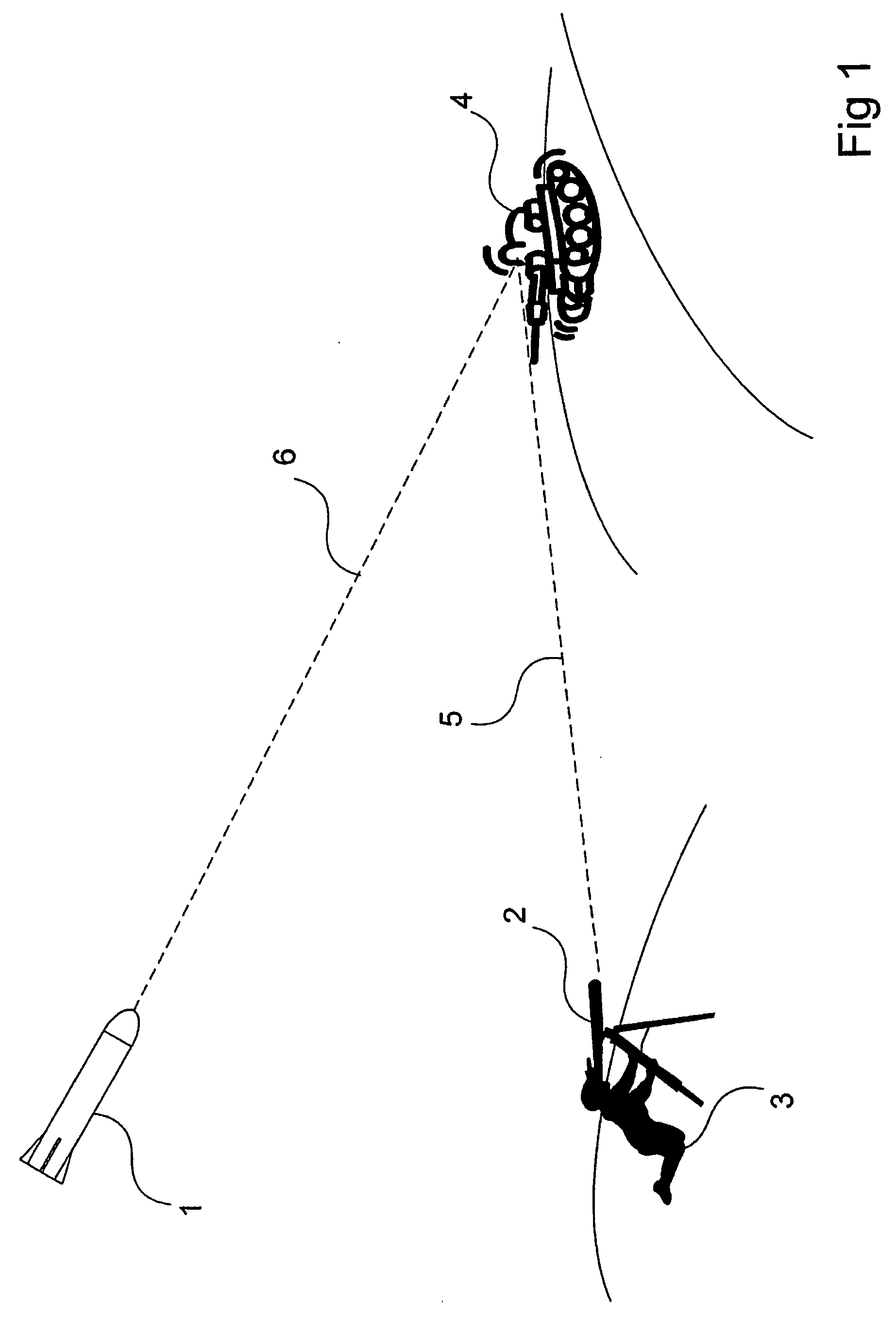
CROSS-REFERENCE TO RELATED APPLICATIONS[0001]This application claims priority to European patent application 05108961.3.TECHNICAL FIELD[0002]The present invention relates to a laser target seeker device. The present invention further relates to a flyable body, for example a missile. The present invention still further relates to a system according for hitting a target. The present invention further relates to a method for detecting a laser beam.BACKGROUND[0003]A common way of providing precision controlled weapons is to point at a target by means of a laser beam and allow a flyable weapon such as a missile, bomb or the like to guide itself towards the laser spot. Consequently a laser target seeker is required, being able to distinguish the reflected laser beam in relation to the background. By laser target seeker a target seeker is intended, the task which is to detect reflected laser beams from a target pointed out in the terrain by means of a laser designator and to determine the ...

Claims


Application Information

Patent Timeline
IPC IPC(8): F41G7/00G01C21/00
CPCF41G7/226G01S3/786F41G7/2293
Inventor LINDGREN, MIKAEL
Owner SAAB AB
Learn More