
Method for manufacturing a product dispensing canister

a technology of product canisters and manufacturing methods, which is applied in the direction of liquid dispensing, packaging under special atmospheric conditions, special packaging, etc., can solve the problems of environmental health hazards, general phase out of propellant gases, and extreme flammability

Inactive Publication Date: 2010-01-07
GARRETT MICHAEL ERNEST
View PDF20 Cites 5 Cited by
  • Summary
  • Abstract
  • Description
  • Claims
  • Application Information

AI Technical Summary

Benefits of technology

[0095]In accordance with the invention, there is provided a method for manufacturing a canister from which product is to be dispensed by means of a dispensing system comprising a solid / gas arrangement in which the gas is adsorbed on to the solid under pressure and desorbed therefrom when the pressure is released and in which the solid comprises an adsorbent for the gas and the gas comprises one or more of nitrogen, oxygen (or mixtures thereof including air), carbon dioxide, nitrous oxide and argon, the canister being adapted to be sealed and having valve means to cause product to be dispensed by means of the pressure of the adsorbed gas, wherein the method includes filling the canister with the gas by applying a pressure of gas to the adsorbent for adsorption thereon via an aperture in the canister and sealing the canister and wherein the sizes of the aperture and of the applied pressure are controlled such that sufficient gas is allowed freely to contact the adsorbent and achieve a pre-determined pressure in the sealed canister.
[0108]Whatever arrangement is employed, the aperture should be sealed as quickly as possible after the gas injection so as to minimize gas leakage from the canister. In particular, it is advantageous for the gas filling pressure to be kept applied until sealing of the aperture has occurred; most preferably, the filling process includes a filling head for the gas supply and has associated therewith means to maintain the aperture seal in place until the filling head is withdrawn.
[0118](i) the flushing of the canister interior with carbon dioxide (or other adsorbent gas) prior to the pressurized gas filling in order in particular to obviate the adiabatic heating of air that would otherwise be present in the canister and thereby prevent any unnecessary and detrimental pressure / temperature rise and additionally to prevent any air adversely affecting the desired pressure ratio in the canister between initial and final product dispense;
[0121]The invention therefore generally allows for a fast gas (and product) filling time together with a precise and critical control of the resulting pressures in the sealed canister during the manufacturing method and subsequently in order to achieve the required start and residual dispense pressures.
[0122]The control of the rise in temperature (and the resulting control of pressures) emanating from the heat of adsorption is possible by the use of the invention generally and is enhanced by the use of blanketed carbon in particular.
[0128]Such a procedure, for bag-in-can canisters in particular, obviates the need for gasification of the adsorbent via the commonly used aperture in the base of the canister and the use of an associated valve / bung to effect closure of that aperture. Indeed, the absence of a base aperture and associated valve / bung renders the canister as a whole less expensive to manufacture in terms both of cost of materials and simplified filling procedures.

Problems solved by technology

However, more recently, such propellant gases have in general been phased out owing to their acknowledged environmentally harmful properties, in particular ozone depletion of the upper atmosphere.
Such gases, however, are by their nature extremely flammable, are environmentally harmful in some respects and in addition can introduce an odor in to the product being dispensed.
However, such attempts have been largely unsuccessful due to the large pressure changes in the canister during use, commonly leading to reduced dispense characteristics at low pressures and a loss of pressure before full product dispense which results in a slow dispense of the last product from the canister.
In addition, it is known that there has been considerable effort to develop further alternative propellant systems for such product dispense.
However, acetone is an aggressive chemical and it was also found that the use of acetone in such systems tended to cause problems associated with chemical attacks of the membrane material and leakage of the acetone through, and around, the membrane resulting in failure of the membrane.
As such, the system as a whole is necessarily very complex due in particular to the need to employ the propellant displacing agent during use and provide means to bring it in to contact with the solid.
Such a bung hole system is not, however, preferred as it may lead to gas leakage from the canister.
Although the blocking process may be reversible in certain cases, displacement by the preferred gas may not be effected completely and therefore would detract from the subsequent adsorption of the gas.
Certain gases, including water vapor, are more strongly held at the carbon adsorption sites than the adsorbed gas and carbon dioxide in particular and therefore should be rigorously excluded from the atmosphere around the carbon; subsequent attempts to dislodge the strongly held gases will not be successful.
Problems may arise, however, in striving to ensure that sufficient gas is introduced in to the canister during its manufacture at a rate which is commensurate with required commercial filling line speeds.
These problems are particularly acute in the present case in that considerably more carbon dioxide is required in the canister due to the presence of adsorbent therein and the amount of gas to be adsorbed thereby.
It has generally been found that the use of techniques currently available to skilled gas technologists are not capable of allowing gasification to occur at speeds required for commercial filling lines.
Using currently commercially available activated carbons, attempts at high speed gasification of canisters have been shown to result in the generation of considerable amounts of heat caused by heat of adsorption and adiabatic heating phenomena.
As a result, attempts to date to effect a speedy gasification, especially in the present case where the adsorbent needs to adsorb considerable amounts of gas, have been inadequate or even generally unsuccessful.

Method used


Image

  • Method for manufacturing a product dispensing canister
  • Method for manufacturing a product dispensing canister
  • Method for manufacturing a product dispensing canister

Examples


Embodiment Construction

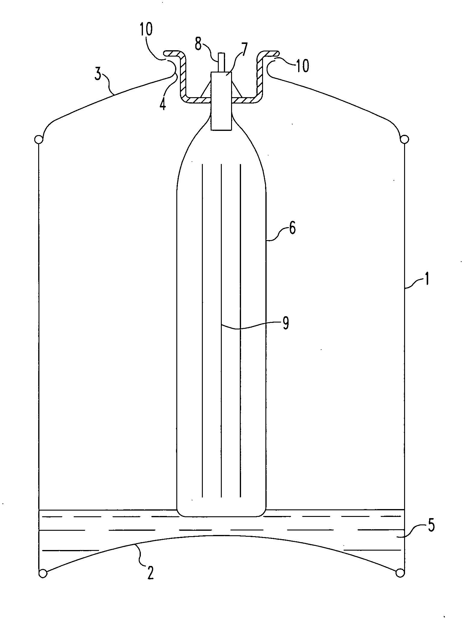
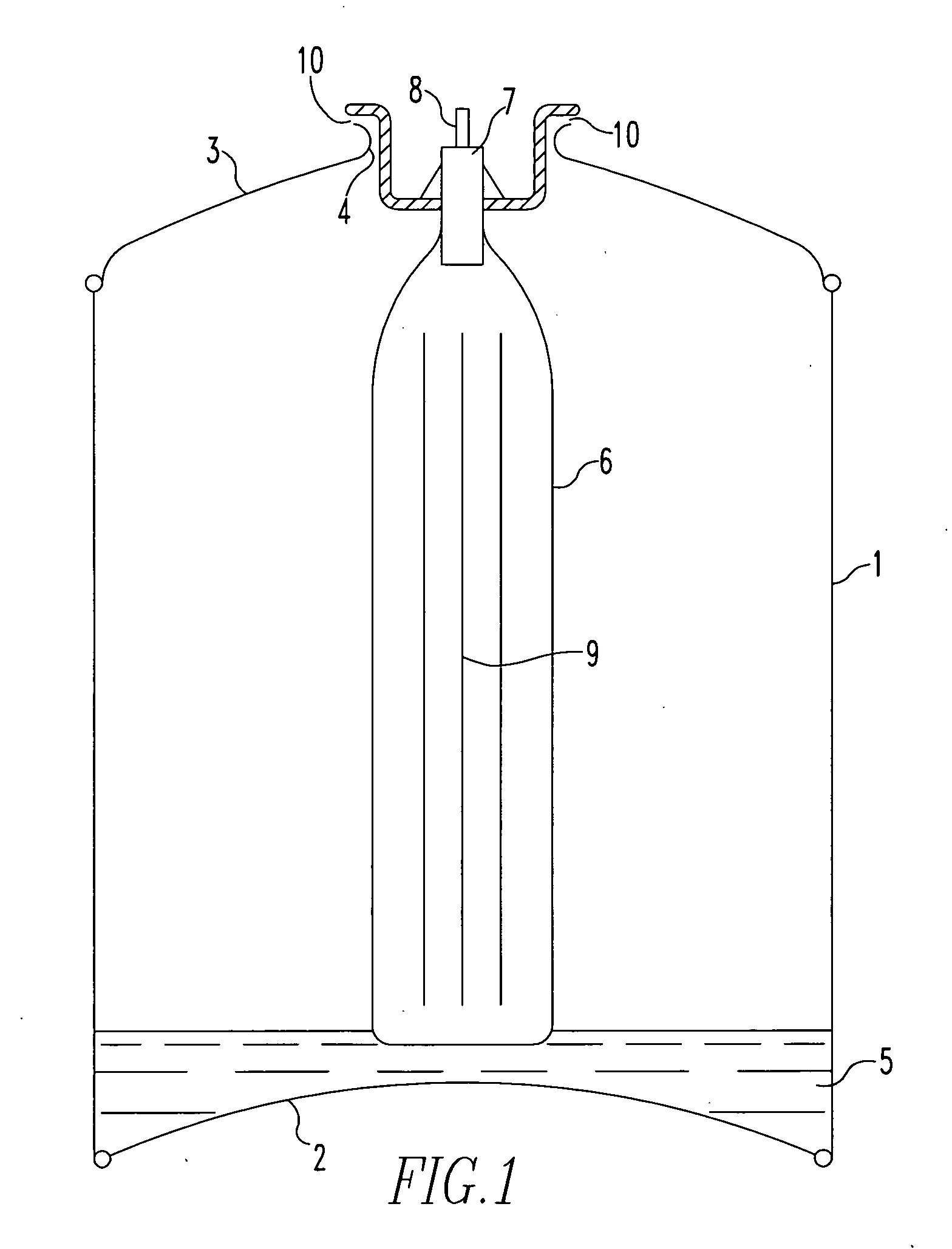
[0141]With reference to the drawings and to FIG. 1 in particular, there is shown a canister comprising a cylindrical main body 1 having a base portion 2 sealingly attached thereto around its base (as shown) perimeter. A canister top portion 3 is sealingly attached to the main body 1 around its upper (as shown) perimeter and has a centrally positioned aperture 4 therein.

[0142]Situated in the lower part of the body 1 and resting on the base portion 2 is a predetermined amount of activated carbon adsorbent 5 that has been pre-saturated / blanketed with a carbon dioxide atmosphere from the time of its manufacture, i.e. activation, until loaded in to the body 1. The interior of the body 1 has previously been flushed with carbon dioxide in order to dispel at least most of the atmosphere therein just prior to the loading of the carbon absorbent 5 therein.

[0143]A ‘bag-on-valve’6 is shown in the drawing in its position at the time of gasification of the canister together with a valve block 7 (...


PUM

PropertyMeasurementUnit
Fractionaaaaaaaaaa
Fractionaaaaaaaaaa
Fractionaaaaaaaaaa

Abstract

A method for manufacturing a canister from which product is to be dispensed by a dispensing system comprising a solid / gas arrangement in which the gas is adsorbed on to the solid under pressure and desorbed therefrom when the pressure is released the solid comprises an adsorbent for the gas, the container being sealed and having valve for dispensing the product. The method includes filling the canister with the gas by applying a pressure of gas to the adsorbent via an aperture in the canister and sealing the canister the size of the aperture and the applied pressure being controlled such that sufficient gas is allowed freely to contact the adsorbent and achieve a pre-determined pressure in the sealed canister.

Description

[0001]This is a Continuation-In-Part Application of pending International patent application PCT / GB2007 / 004159 filed Oct. 31, 2007 and claiming the priority of UK patent application 06 21881.2 filed Nov. 2, 2006.BACKGROUND OF THE INVENTION[0002]This invention relates to systems for dispensing substances from containers and, more particularly, to a method of t manufacturing canisters for such systems.[0003]A large number of products are on the general market packaged in canisters—some of which cause the product to be dispensed therefrom in the form of small or atomized particles and are therefore commonly referred to as ‘aerosols’. The particles can be dispensed from the canister by means of a gas (or vapor) pressure generated in situ in the canister, and acting as a dispensing or propellant gas. Such products include ones for personal care including hair sprays, shaving creams, deodorants and the like and ones for household use including cleaning substances, room fragrances, insect ...

Claims


Application Information

Patent Timeline
IPC IPC(8): B23P11/00
CPCY10T29/49826B65D83/62B65B31/003F17C5/06
Inventor GARRETT, MICHAEL ERNEST
Owner GARRETT MICHAEL ERNEST
Learn More