
Gas Analyzer and Gas Analyzing Method

a gas analyzer and gas analysis technology, applied in the field of gas analyzers, can solve the problem of inability to conduct real-time analysis of exhaust gas, and achieve the effect of reducing the amount of data input to the analyzer

Inactive Publication Date: 2009-12-31
TOYOTA JIDOSHA KK +1
View PDF29 Cites 22 Cited by
  • Summary
  • Abstract
  • Description
  • Claims
  • Application Information

AI Technical Summary

Benefits of technology

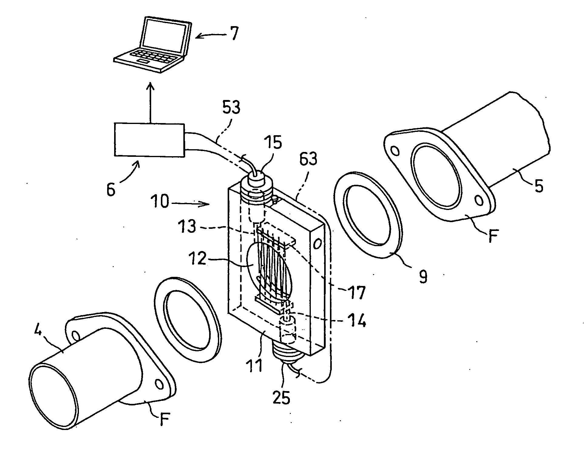
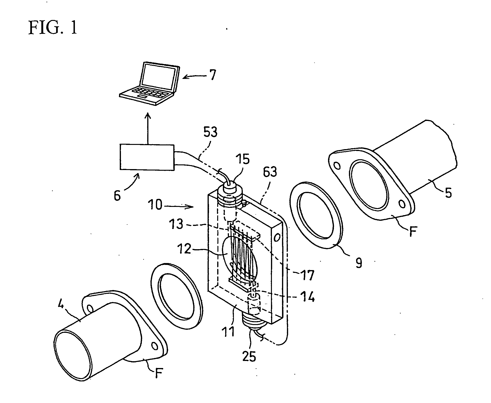
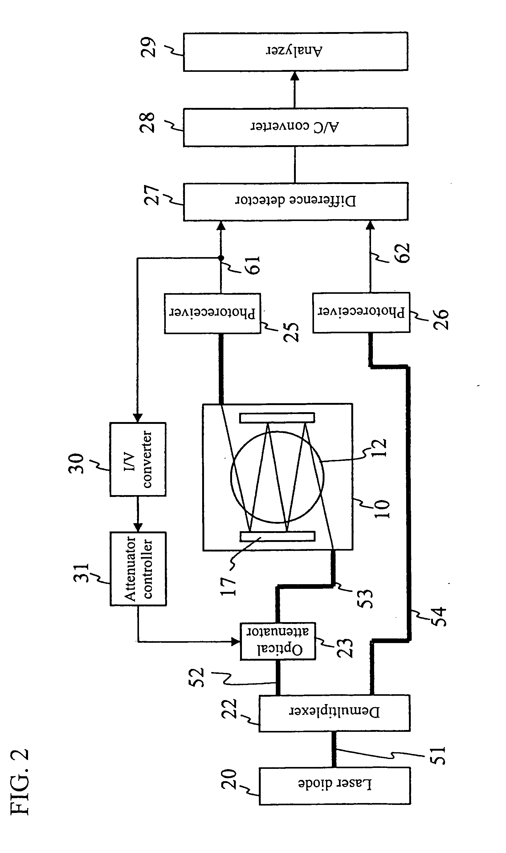
[0025]According to the present invention, gas is emitted with measurement laser light via an optical attenuator, and control is conducted by the above-stated optical attenuator so that the light intensity of the measurement laser light that has passed through the gas has a predetermined relationship with the light intensity of the reference laser light. Therefore, there is no need to input data of the light intensity of the measurement laser light that has passed through the gas to an analyzer. Thus, the data amount to be input to the analyzer can be reduced, which is for analyzing a concentration or the like of a gas component contained in the gas based on the measurement laser light that has passed through the gas and the reference laser light that does not pass through the gas. As a result, concentrations of a plurality of types of gas components contained in the gas can be analyzed for measurement at a plurality of positions in real time.

Problems solved by technology

Although the above-stated exhaust gas analyzer described in Patent Document 1 can facilitate measuring the THC in exhaust gas of a vehicle when the vehicle is moving on a real road, it is impossible to conduct analysis of the exhaust gas in real time because the exhaust gas has to be transferred for analysis of gas components from the exhaust path of the engine to an analysis section through a pipe.

Method used


Image

  • Gas Analyzer and Gas Analyzing Method
  • Gas Analyzer and Gas Analyzing Method
  • Gas Analyzer and Gas Analyzing Method

Examples


embodiment 2

[0077]FIGS. 3 and 4 illustrate Embodiment 2 of the present invention, in which FIG. 3 illustrates the major configuration of an embodiment where a gas analyzer is mounted in an engine bench, and FIG. 4 is a block diagram illustrating the overall configuration of the gas analyzer including the major configuration of a laser oscillation / photoreceiving controller and a signal analyzer. In the present embodiment, sensor units are provided at three positions along an exhaust path, and at each of the positions, a gas component contained in exhaust gas and a concentration thereof are analyzed for measurement, and the gas analyzer includes a plurality of sensor units 10A, 10B, and 10C provided at three positions along the exhaust path. The first sensor unit 10A is provided between a first catalyst device 8A and an upstream exhaust tube 4 on an engine 2 side, the second sensor unit 10B is provided downstream of the first catalyst device 8A and the third sensor unit 10C is provided downstream...

embodiment 3

[0081]FIG. 5 illustrates a gas analyzer of the present invention, where a sensor unit is provided at one position of an exhaust path to measure concentrations of NO (nitric monoxide) and oxygen (O2) contained in exhaust gas.

[0082]A wavelength of laser light passing through the gas is set in accordance with a gas component to be detected, for example, the wavelength suitable for the detection of oxygen (O2) is 760 nm, the wavelength suitable for the detection of ammonia is 1530 nm, the wavelength suitable for the detection of carbon monoxide is 1560 nm, and the wavelength suitable for the detection of nitric monoxide (NO) is 1796 nm.

[0083]Since the wavelength suitable for the detection of oxygen (O2) is far away from the wavelength suitable for the detection of NO, it is impossible for one laser diode to emit light including the both wavelengths.

[0084]Thus, a laser oscillation controller 6 includes a NO laser diode 33 that emits laser light to measure the concentration of NO, and an...

embodiment 4

[0100]FIG. 6 illustrates a gas analyzer of the present invention, which is configured so that sensor units 10A, 10B, and 10C are provided at three positions along an exhaust path to measure concentrations of NO (nitric monoxide) and oxygen (O2) contained in exhaust gas.

[0101]In the present embodiment, a NO demultiplexer 122 demultiplexes laser light emitted from a NO laser diode 33 into six laser light beams, which are then sent to the respective measurement positions as NO measurement light or NO reference light. Further, an oxygen demultiplexer 222 demultiplexes laser light emitted from an oxygen laser diode 34 into six laser light beams, which are then sent to the respective measurement positions as oxygen measurement light or oxygen reference light. Optical attenuators 323A, 323B, and 323C that attenuate the NO reference light demultiplexed by the NO demultiplexer 122 each has a set attenuation ratio such that their light intensities of the NO reference light can be made equal ...


PUM


Abstract

A gas analyzer capable of measuring a concentration of a gas component in gas at sensor units provided at a plurality of positions in real time by decreasing the number of signals input from the sensor units to an analyzer so as to reduce a data amount input to the analyzer and a gas analyzing method. The gas analyzing method includes the steps of: demultiplexing laser light by a demultiplexer into measurement laser light and reference laser light; letting the measurement laser light pass through gas to be received by a photoreceiver; finding an absorption spectrum absorbed by a gas component in the gas based on a light intensity of the received measurement laser light and of the reference laser light; and analyzing the absorption spectrum to measure a concentration of the gas component.

Description

TECHNICAL FIELD[0001]The present invention relates to a gas analyzer, and more particularly relates to a gas analyzer and a gas analyzing method, capable of determining a concentration or the like of a gas component contained in gas flowing through a gas flowing path such as an exhaust path of an engine in real time.BACKGROUND ART[0002]Conventionally, a vehicle-mounted HC measurement device described in JP Published Patent Application No. 2004-117259 A (Patent Document 1) is available as an exhaust gas analyzer for car or the like. This vehicle-mounted HC measurement device is adapted to allow a NDIR (non-dispersive infrared spectroscopy) gas analyzer, an exhaust gas flowmeter and an arithmetic operation circuit to be installed in a vehicle, the NDIR for continuously measuring a HC (hydrocarbon) concentration in exhaust gas flowing through an exhaust tube connected with an engine, the exhaust gas flowmeter continuously measuring a flow rate of the exhaust gas flowing through the exh...

Claims


Application Information

Patent Timeline
IPC IPC(8): G01N21/17G01N21/00G01N21/3504G01N21/35G01N21/359
CPCG01N21/031G01N21/3504G01N21/3151
Inventor YAMAKAGE, MASAHIROGOTO, KATSUTOSHIMUTA, KENJIDEGUCHI, YOSHIHIROASAMI, SHINICHIROFUKADA, SATOSHI
Owner TOYOTA JIDOSHA KK
Learn More