
Wave soldering tank

a soldering tank and wave technology, applied in the direction of non-electric welding apparatus, manufacturing tools, solventing apparatus, etc., can solve the problems of molten solder splatter, high labor intensity, and difficulty in practical application, and achieve the effect of convenient and safe removal and high degree of practicality

Active Publication Date: 2009-12-31
SENJU METAL IND CO LTD
View PDF3 Cites 8 Cited by
  • Summary
  • Abstract
  • Description
  • Claims
  • Application Information

AI Technical Summary

Benefits of technology

[0025]The object of the present invention is to provide a wave soldering tank with excellent utility enabling it to be stably used for long periods, on which maintenance operations can be efficiently performed, which does not have fluctuations in the height of spouting, and which does not damage the rotating shaft of a discharge pump.
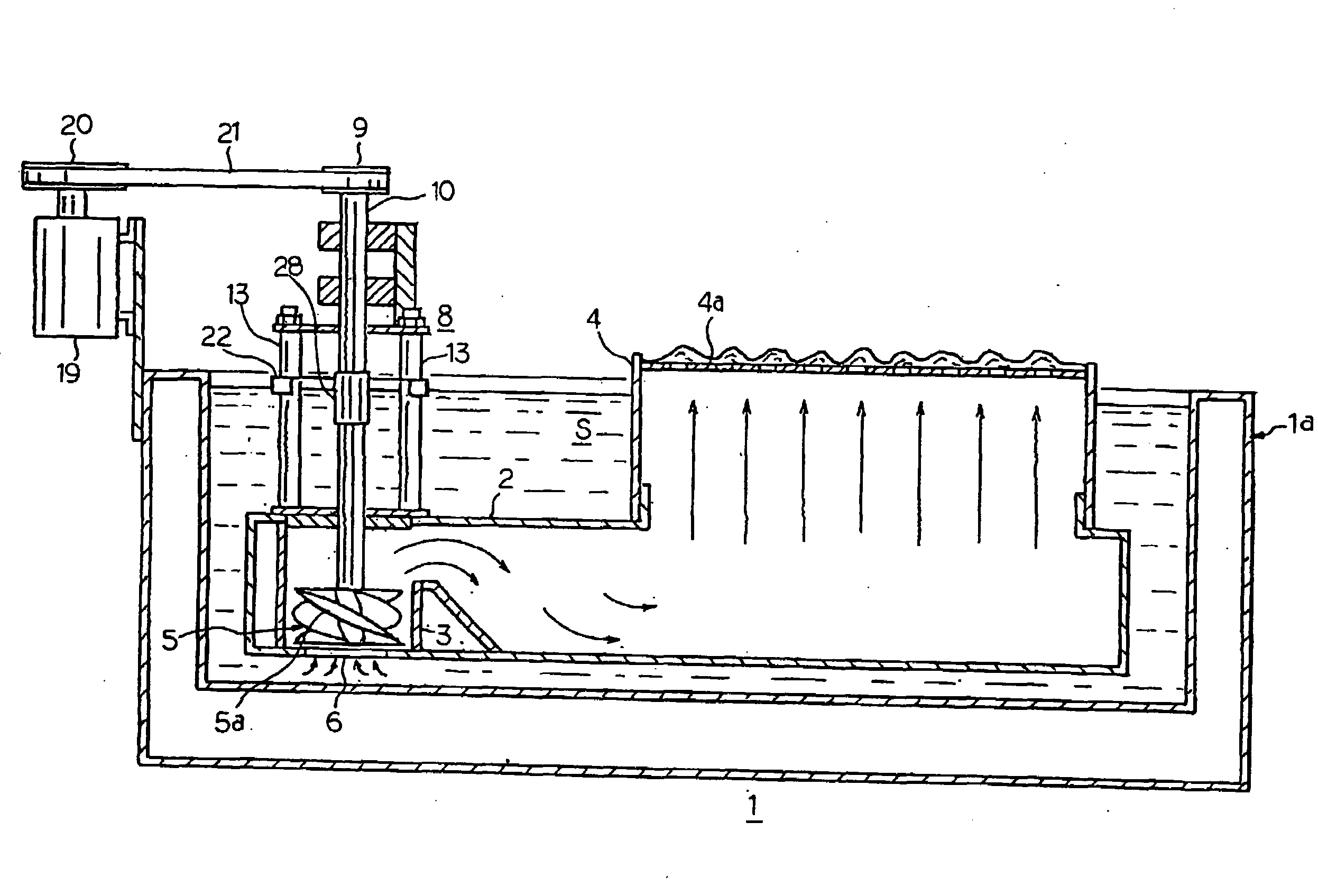
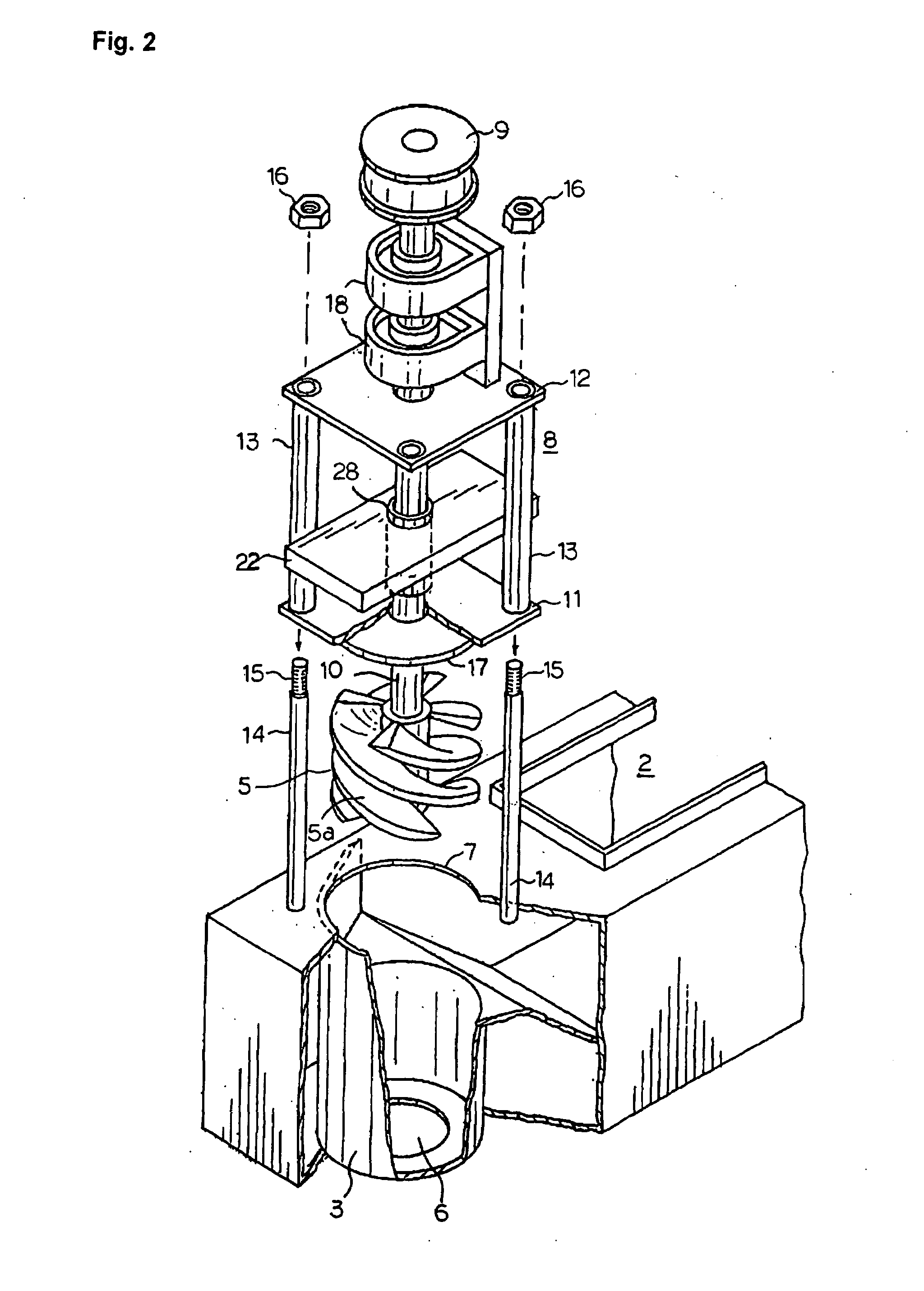
[0033]In a wave soldering tank according to the present invention, since the periphery of the rotating shaft of the discharge pump is covered by an oxidation preventing member, the formation of oxides in the periphery of the rotating shaft of the discharge pump is suppressed. In addition, the size of the oxidation preventing member in a wave soldering tank according to the present invention is such that the oxidation preventing member is not affected by molten solder which drops from the discharge nozzle and such that the oxidation preventing member does not oscillate, as a result of which the height of the surface of molten solder contained in the wave soldering tank does not fluctuate. Even if the oxidation preventing member itself oscillates, as the horizontal area of the oxidation preventing member is relatively smaller than the horizontal area of the wave soldering tank, it does not cause the height of the surface of the entirety of the molten solder housed in the wave soldering tank to fluctuate.
[0034]Therefore, a wave soldering tank according to the present invention does not produce fluctuation in the height of spouted solder. In addition, the oxidation preventing member can be easily and safely removed when performing maintenance of the wave soldering tank. Therefore, the wave soldering tank has a high degree of practicality lacking in a conventional wave soldering tank.

Problems solved by technology

The invention disclosed in Patent Document 4 has the following problems (i)-(iii) in its practical application, and these make its practical application difficult.
If the oxidation preventing member is accidentally dropped onto the molten solder, the molten solder will splatter and expose the maintenance workers to an extremely dangerous situation.
As a result, this maintenance operation requires a considerable number of man hours.
(iii) When the oxidation preventing member causes oscillation of the surface of the molten solder, the insertion hole for the rotating shaft of the discharge pump rubs against the rotating shaft and the rotating shaft is damaged.
When the oxidation preventing member, which is large and heavy, even lightly contacts the rotating shaft of the discharge pump, it damages the rotating shaft of the discharge pump.
If the rotating shaft of the discharge pump is damaged, molten solder adheres to the damaged portion, and components of the rotating shaft diffuse into the molten solder from the damaged portion, causing so-called leaching to develop.

Method used


Image

  • Wave soldering tank
  • Wave soldering tank
  • Wave soldering tank

Examples


example 1

[0098]The present invention will be explained more specifically while referring to an example.

[0099]Soldering of printed circuit boards was carried out using an automatic soldering apparatus according to the present invention incorporating the wave soldering tank shown in FIGS. 1-6.

[0100]Here, the length Lx between the inner sides of the connecting rods 13e, 13d in FIG. 4 was 64 mm, the length Ly between the inner sides of connecting rods 13d, 13f was 88 mm, and the diameter of the rotating shaft 10 was 20 mm. The oxidation preventing member 22 had short sides with a length X of 60 mm and long sides with a length Y of 110 mm. The separation between the top plate 23 and the bottom plate 24 in FIG. 5 was 13 mm, through holes 25 having a diameter of 20.5 mm were formed at approximately the center of the top plate 23 and the bottom plate 24, and a hollow portion 26 having a square transverse cross section measuring 12 mm on a side was formed on the periphery of the interior of the oxida...


PUM

PropertyMeasurementUnit
specific gravityaaaaaaaaaa

Abstract

A wave soldering tank is provided on which it is easy to perform maintenance, which does not have fluctuation of the height of spouted solder, which does not damage the rotating shaft of a discharge pump, and which can be stably used for long periods.The wave soldering tank 1 has a tank body 1a which houses molten solder S, a discharge pump 5 which pumps molten solder S, a discharge nozzle 4 which spouts molten solder S which was sent to it by the discharge pump 5 upwards, a duct 2 having the discharge pump 5 installed at one of its ends and the discharge nozzle 4 installed at its other end, an oxidation preventing member 22 which has a prescribed size and which floats on the surface of the molten solder S, and an engaging means 13 which controls rotation of the oxidation preventing member 22 in a horizontal plane. The oxidation preventing member 22 has a surrounding member 28 which extends downwards at its center and which surrounds the rotating shaft 10 with a gap between it and the rotating shaft 10, and a hollow space 26 in its interior for providing buoyancy.

Description

TECHNICAL FIELD[0001]This invention relates to a wave soldering tank, and specifically, it relates to a wave soldering tank which is installed in an automatic soldering apparatus to carry out soldering of printed circuit boards.BACKGROUND ART[0002]In an automatic soldering apparatus, various processing devices such as a fluxer, a preheater, a wave soldering tank, and a cooler are successively installed in the direction of travel of a conveyor which is installed above these processing devices. As a printed circuit board is being transported by the conveyor, it has flux applied to it by the fluxer, it is preheated by the preheater, it undergoes soldering in the wave soldering tank, and it is cooled by the cooler to perform soldering. Each of these processing devices affects the quality of soldering, but the effect of the wave soldering tank is particularly great.[0003]A wave soldering tank carries out soldering of a printed circuit board by contacting the bottom surface of a printed c...

Claims


Application Information

Patent Timeline
Patent Type & Authority Applications(United States)
IPC IPC(8): B23K3/06
CPCB23K3/0653B23K1/0016B23K1/08H05K3/34B23K2101/42
Inventor ZEN, MITSUOICHIKAWA, HIROKAZUOZAWA, SATOSHI
Owner SENJU METAL IND CO LTD
Learn More