Eureka AIR delivers breakthrough ideas for toughest innovation challenges, trusted by R&D personnel around the world.

Bendable end-effector

Inactive Publication Date: 2015-11-19
KOHYOUNG TECH +1
View PDF6 Cites 1 Cited by
  • Summary
  • Abstract
  • Description
  • Claims
  • Application Information

AI Technical Summary

Benefits of technology

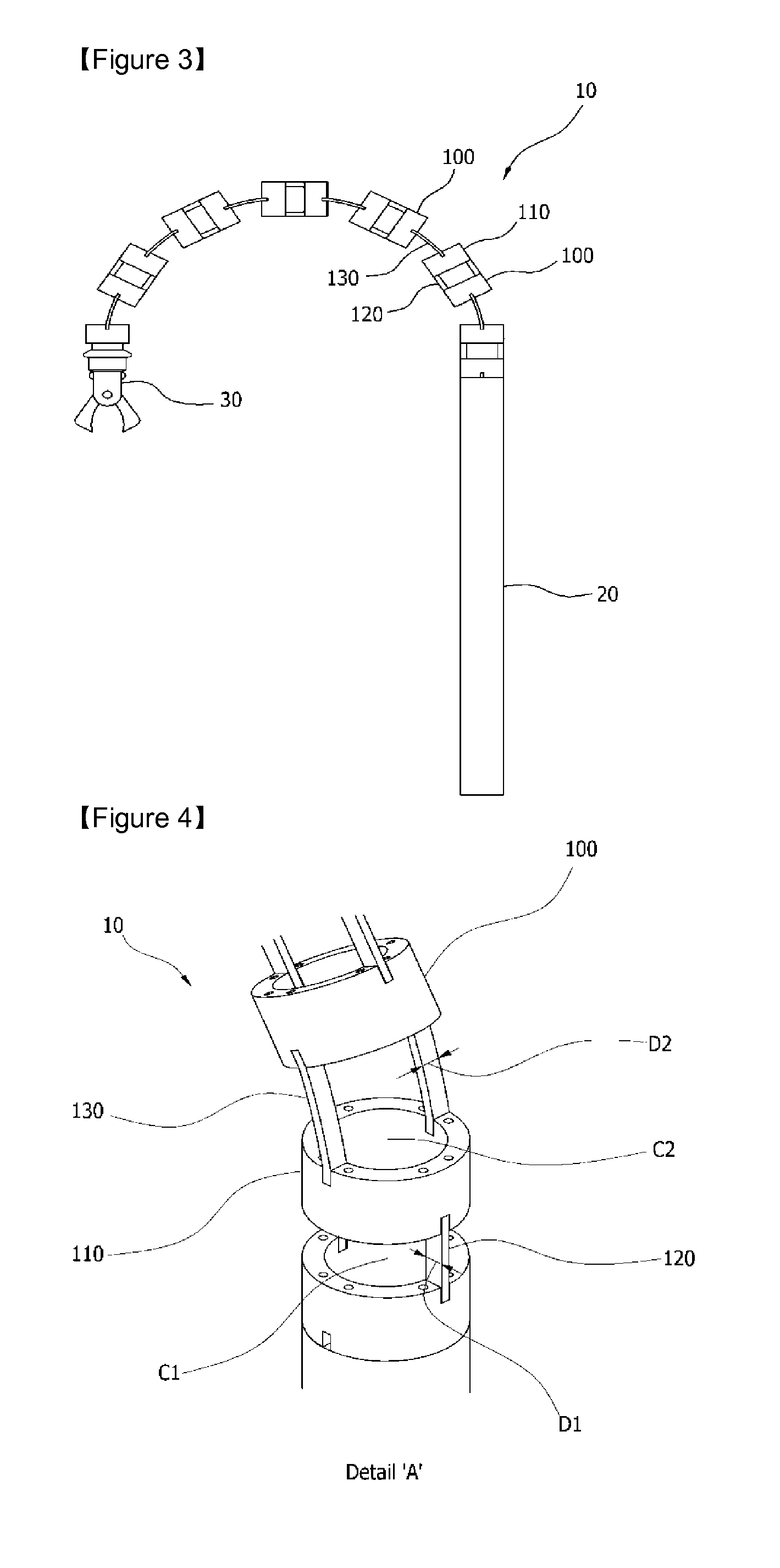
The present invention provides a bendable end-effector for endoscopic surgery that allows for bending in longitudinal or transverse direction over 180 degrees without changing tip, extending the range of endoscopic surgery. The design allows for the removal of lesions in various angles safely and easily during endoscopic surgery. The bendable end-effector allows for the use of a wider range of surgical instruments and facilitates the removal of curved or hard-to-reach lesions. The design also has better restoring force and supports more power than conventional end-effector designs, ensuring safe and effective use during surgery.

Problems solved by technology

But, there is a problem that endoscope and surgical instrument are difficult to access body parts, such as paranasal sinuses, and to be applied ENT endoscopic surgery due to a human body structure characteristic.
There is a problem that an end-effector are not made of flexible material since a surgical instrument should transmit force to operate, in which the surgical instrument used in ENT endoscopic surgery are biopsy, forceps, shaver, suction, and scissors.
Especially, it is a problem that there are inaccessible areas to reach, or have to operate punching treatment externally when a lesion exists in anterior and inferior region of maxillary sinus and interior of frontal sinus.
But, such conventional end-effectors including plurality of cylinders using coil spring, has an limited angle capable to bend, maximum to 90 degree, also has a problem that it can't be used in a fine crusher for curved areas since a force to support the coil spring is restricted, is a force of restitution to original state is weak, and as well as, it is restrictive to obtain enough area in the interior when coupling the coil spring and the cylinder due to its structure characteristic.

Method used


Image

  • Bendable end-effector
  • Bendable end-effector
  • Bendable end-effector

Examples


Embodiment Construction

[0041]The present invention is described more fully hereinafter with reference to the accompanying drawings, in which example embodiments of the present invention are shown.

[0042]The present invention may, however, be embodied in many different forms and should not be construed as limited to the example embodiments set forth herein. Rather, these example embodiments are provided so that this disclosure will be thorough and complete, and will fully convey the scope of the present invention to those skilled in the art. In the drawings, the sizes and relative sizes of layers and regions may be exaggerated for clarity.

[0043]It will be understood that, although the terms first, second, third etc. may be used herein to describe various elements, components, regions, layers and / or sections, these elements, components, and / or sections should not be limited by these terms. These terms are only used to distinguish one element, component, region, layer or section from another region, layer or ...


PUM


Abstract

A bendable end-effector is described, used in endoscopic surgery which requires very large refraction angle, being capable of obtaining large internal space, as well as, transmitting safely a torque to a surgical instrument in curved state. The bendable end-effector includes a fixing block coupled at a driving unit, a bendable block coupled to the end of the fixing block and bending to a user's desired direction and angle, and a surgical instrument coupled to the end of the bendable block.

Description

TECHNICAL FIELD [0001]Exemplary embodiments of the present invention relate to a bendable end-effector. More particularly, exemplary embodiments of the present invention relate to a bendable end-effector for an endoscopic surgery in otolaryngology such as paranasal sinuses.BACKGROUND ART [0002]In general, an endoscopic surgery operates a surgery while watching an affected area of a patient through an image taken by an endoscope, in which surgical instruments and an endoscope camera are installed through a small hole, without making large incision.[0003]Endoscopic surgery, started from laparoscopic surgery, has an advantage of a fast recovery time of surgical patients compared with open surgery since the incision is small and less bleeding.[0004]Recently, endoscopic surgery system is technically developed enough to be used almost in all type of open surgery as well as it has being increasing in other field of medicine.[0005]Meanwhile, otolaryngology, a branch of medical science, hand...

Claims


Application Information

Patent Timeline
IPC IPC(8): A61B1/005A61B17/22A61B1/00
CPCA61B1/0058A61B17/22A61B1/00085A61B17/29A61B2017/00314A61B2017/00327A61B17/32002A61B1/00087A61B1/0055A61B1/0057A61B1/233A61B1/267A61B17/24
Inventor YOON, HYUN-SOOYI, BYUNG-JU
Owner KOHYOUNG TECH
Why Eureka
Eureka Blog
Learn More