Variable rate particle counter and method of use

Inactive Publication Date: 2007-05-08
SIEMENS HEALTHCARE DIAGNOSTICS INC
View PDF11 Cites 1 Cited by
  • Summary
  • Abstract
  • Description
  • Claims
  • Application Information

AI Technical Summary

Benefits of technology

[0010]It is, therefore, among the objects of the present invention to provide a method and apparatus capable of improving the precision of analyses of test sam

Problems solved by technology

One of the disadvantages of such known devices is that they operate with a very limited dynamic range.
At low counts, precision suffers and at high counts coincident events (for example, where several cells passing at the same time through the device are counted as one cell or event) limit the range.
Techniques involving multiple counts where repetitive delivery of a predetermi

Method used


Image

  • Variable rate particle counter and method of use
  • Variable rate particle counter and method of use
  • Variable rate particle counter and method of use

Examples


Example

DETAILED DESCRIPTION OF THE DRAWINGS

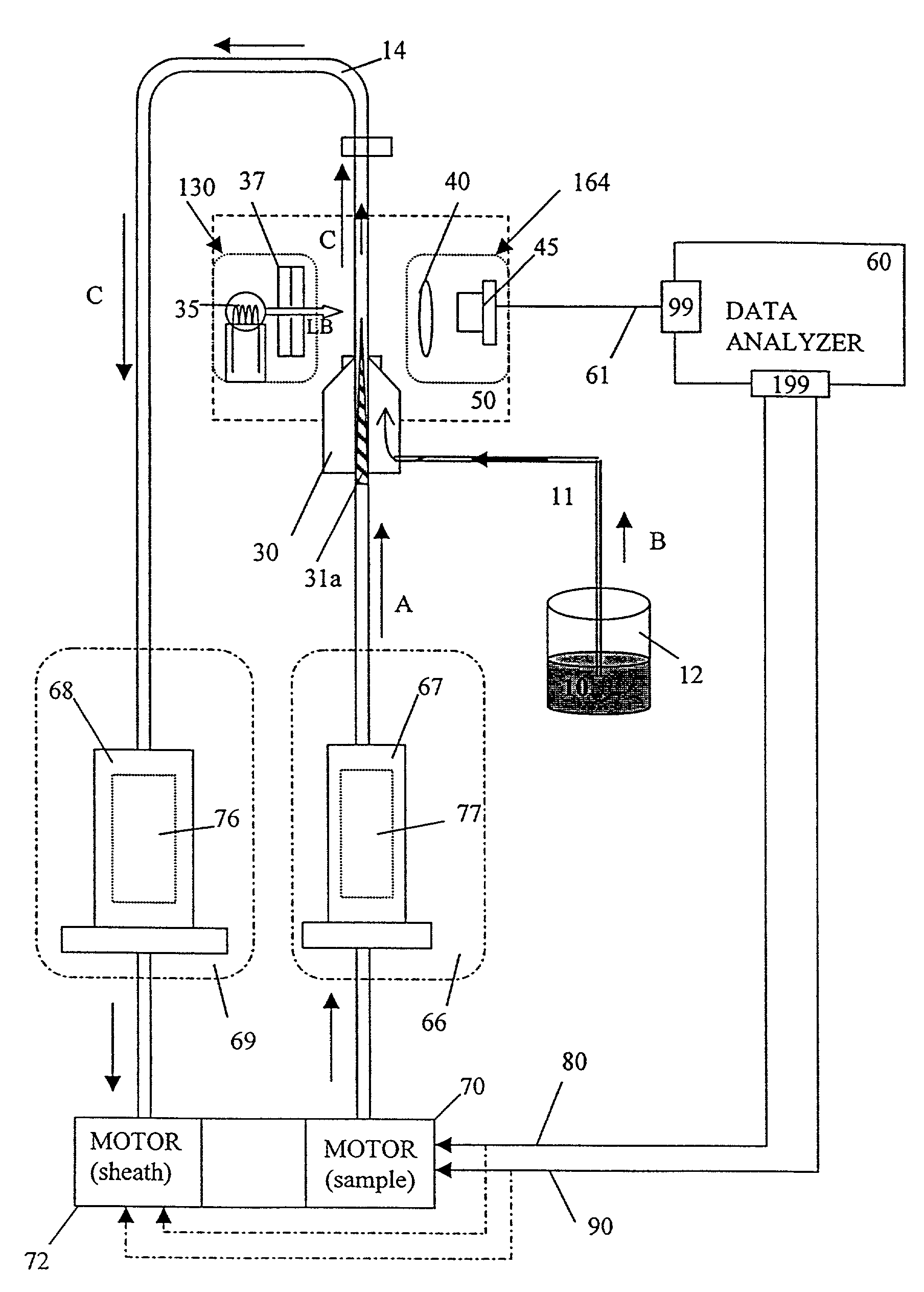
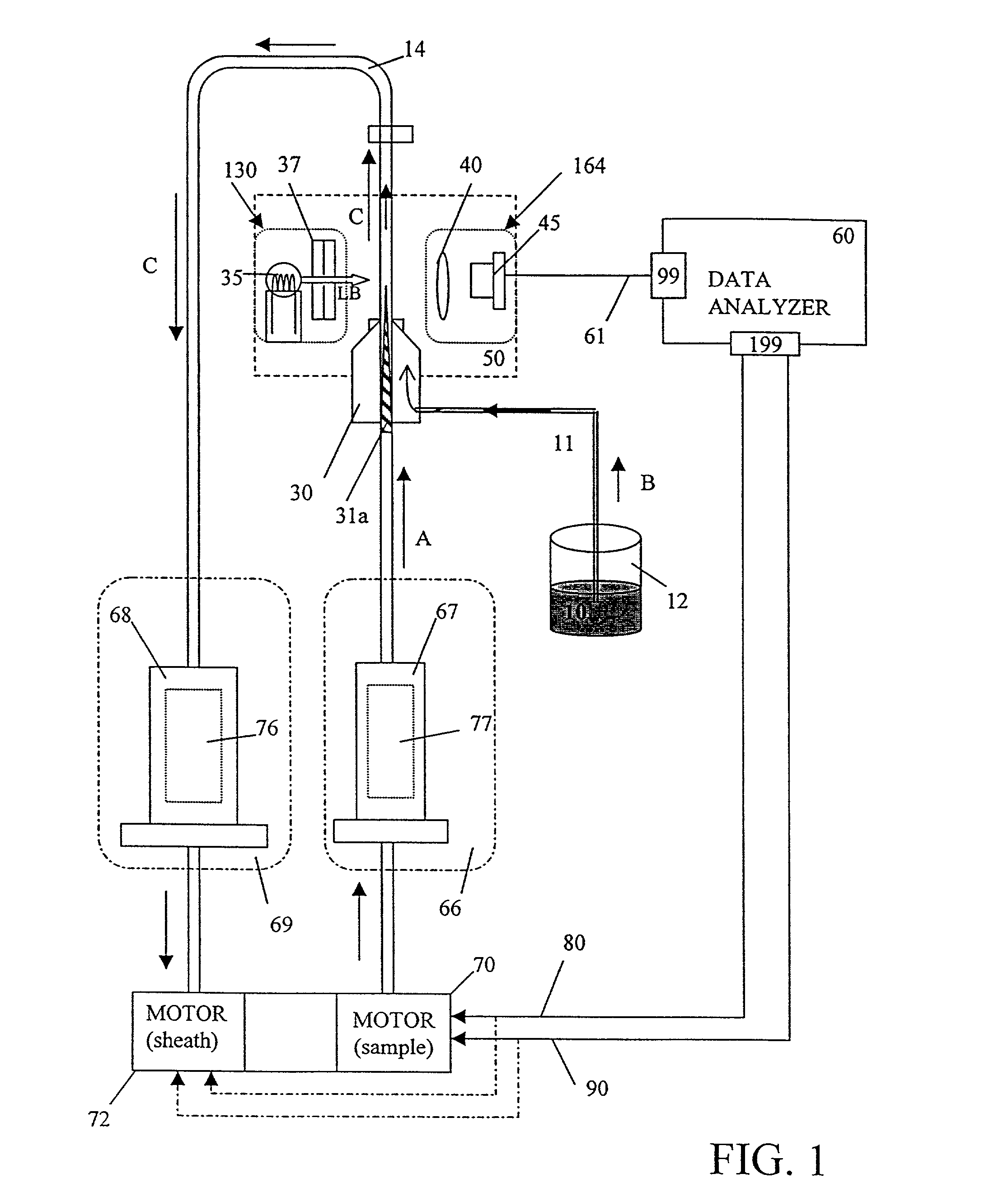
[0016]Referring to FIG. 1, a variable rate volumetric particle counter (“VRVPC”), in accordance with a preferred embodiment of the present invention, is shown. The VRVPC includes a sheath flow cell 30 which provides a thin stream of particles in suspension for analysis by a detection assembly. It should be recognized that the stream of particles is any fluid concentration of particles, preferably cells such as blood cells.

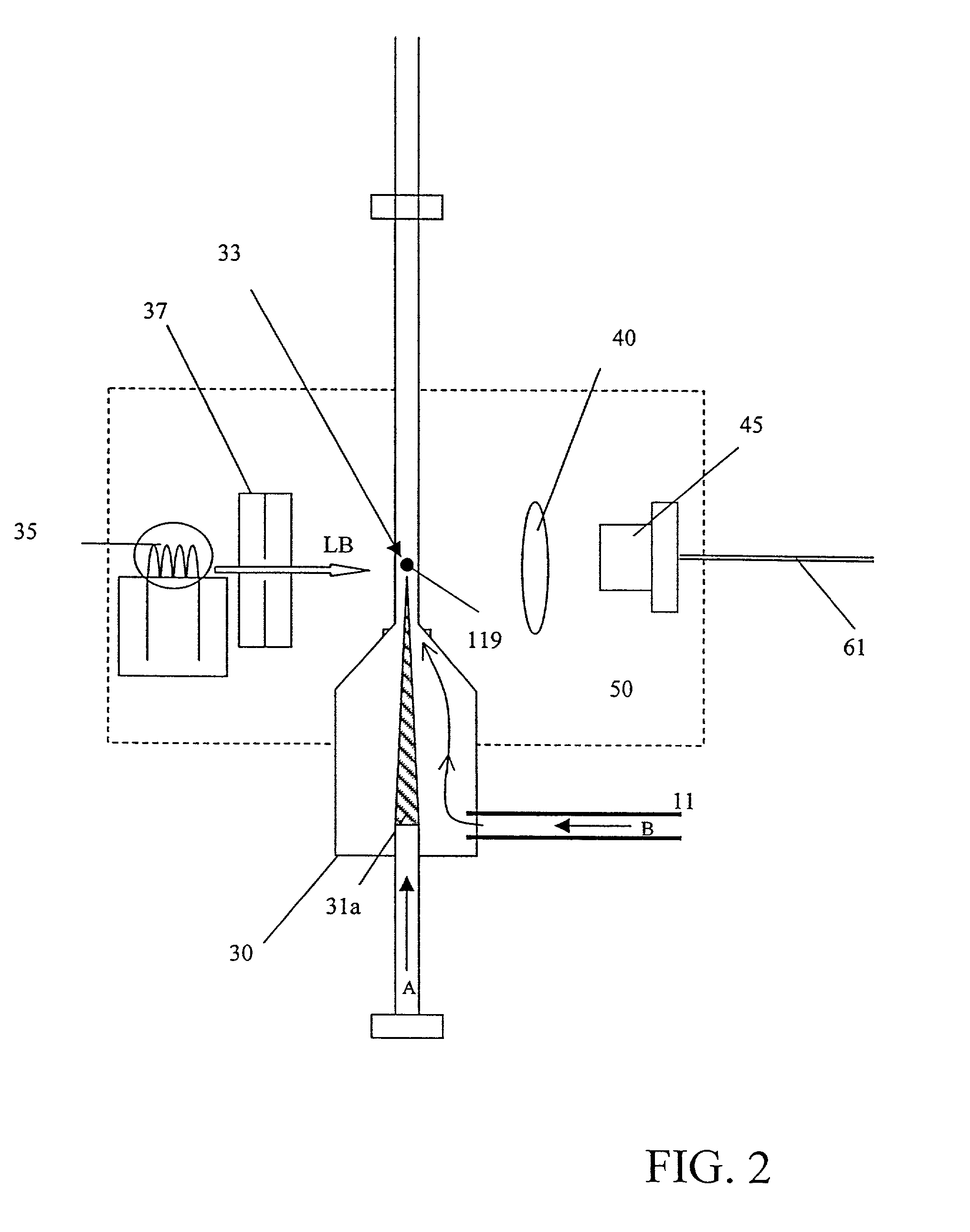
[0017]Sheath flow cell 30 allows presentation of cells or particles, prepared in a reaction mixture as is known, essentially one cell at a time positioned for access by detection assembly 50. The reaction mixture is drawn through a nozzle 31a into the center of a laminar flow stream 33 of a sheath liquid 10 forming a suspension of the mixture in the sheath fluid stream (a “cell suspension”). The flow velocity of the sheath liquid {dot over (Q)}SH is controlled to be much greater than the velocity of {dot over (Q)}S of the introdu...


PUM


Abstract

A variable rate particle counter for adjusting the volumetric delivery rate of fluid to a flow cell based upon an initial particle count rate in order to effectively “tune” the final dilution of sample sheath flow to the particle concentration of the sample. A sheath fluid syringe pump and a test sample syringe pump are driven by motors which are adjusted by a data analyzer. The data analyzer compares a particle count rate measured by a detection assembly to a predetermined reference value and determines if the count rate is too high or to low. Accordingly, one of several pump profiles is initiated to adjust the flow rate of the sheath fluid or test sample or both. Advantageously, the low cell count precision is improved and the upper limit cell count is expanded.

Description

RELATED APPLICATIONS[0001]This application is a divisional application of U.S. Ser. No. 09 / 225,937, filed Jan. 6 1999 now abandoned.[0002]This application is related to U.S. application Ser. No. 08 / 688,517, which issued as U.S. Pat. No. 5,788,927 on Aug. 4, 1998 for “Unified Fluid Circuit Assembly For A Clinical Hematology Instrument”, which patent is commonly owned by the assignee of the present application, Bayer Corporation, and which is incorporated herein by reference in its entirety.FIELD OF THE INVENTION[0003]The present invention relates to instruments for performing clinical analyses of samples, more particularly to improving the counting precision of such instruments by varying the delivery rate of the samples.BACKGROUND OF INVENTION[0004]Analytical instruments are well known and have been commercially available for many years, in different constructions, for performing a variety of test analyses by various methods.[0005]These instruments, such as clinical hematology lab i...

Claims


Application Information

Patent Timeline
IPC IPC(8): G01N21/00G01N15/00G01N15/14
CPCG01N15/1404Y10T436/25Y10T436/11Y10T436/101666
Inventor FARRELL, GREGORY A.
Owner SIEMENS HEALTHCARE DIAGNOSTICS INC
Why Eureka
Try Eureka