
Water repellent catalyst layer for polymer electrolyte fuel cell and manufacturing method for the same

a technology of electrolyte fuel cell and catalyst layer, which is applied in the direction of primary cells, electrochemical generators, cell components, etc., can solve the problems of flooding phenomenon, power generation finally stops, and the voltage is gradually reduced, so as to improve the evacuation performance of produced water and the catalyst utilization ratio

Inactive Publication Date: 2009-12-17
CANON KK
View PDF1 Cites 4 Cited by
  • Summary
  • Abstract
  • Description
  • Claims
  • Application Information

AI Technical Summary

Benefits of technology

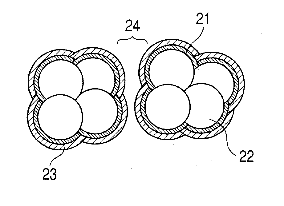
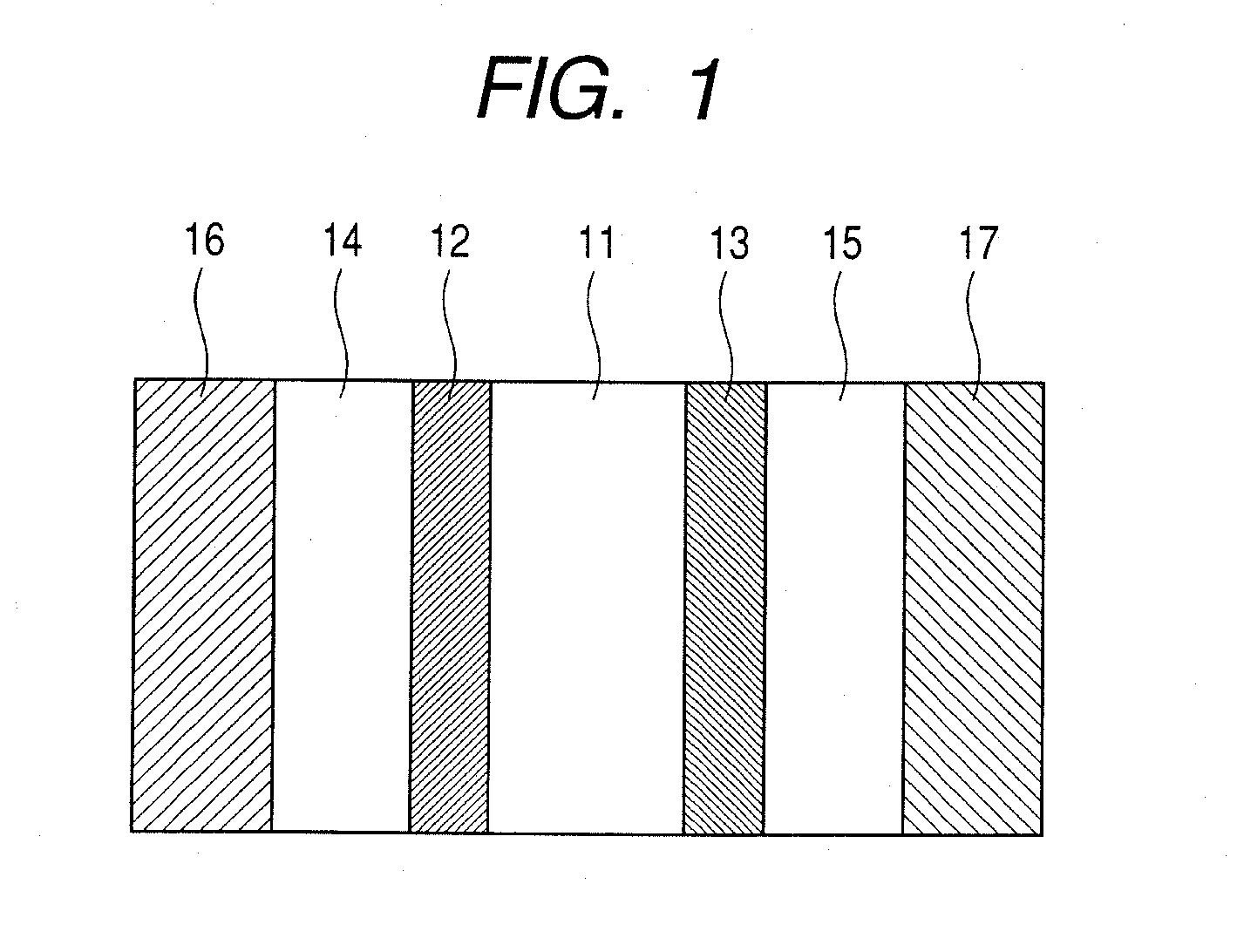
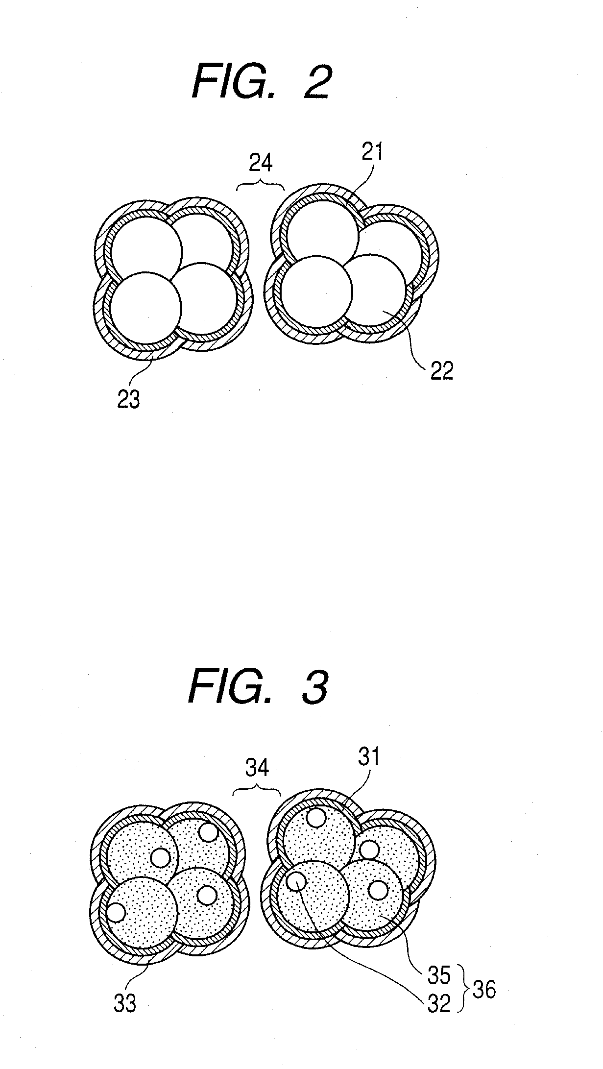
[0009]The present invention has been made in view of the above-mentioned problems, and it is an object of the present invention to provide a water repellent catalyst layer for a polymer electrolyte fuel cell, which imparts a hydrophobic property to entire space in a catalyst layer, including micro spaces, to improve the evacuation performance of the produced water and a catalyst utilization ratio, and a manufacturing method therefor.

Problems solved by technology

In this case, there is a problem in that a voltage is gradually reduced as power generation time elapses, and power generation finally stops.
In particular, the flooding phenomenon is liable to occur in the catalyst layer on a cathode side, where the water is generated.
However, this method has a problem in that the three-phase interface is reduced due to the presence of the PTFE particles, so that output power is also reduced.
However, in this method, when the PTFE particles are subjected to a glass transition, the Nafion (registered trademark) is decomposed, so an improvement in performance cannot be realized.
As a result, even though the hydrophobic property of the catalyst layer using the hydrophobic particles is improved, there is a problem in that some of the hydrophobic particles enter a space between the catalyst and the electrolyte or between the catalyst fine particles, and an effective surface area decreases, thereby reducing a catalyst utilization ratio and catalyst layer performance.
Accordingly, there is a problem in that an inside of the space having a diameter smaller than 100 nm (hereinafter referred to as “micro space”) cannot be made hydrophobic in theory.
Accordingly, there is a problem in that when the outside of the micro space is made hydrophobic, the produced water is trapped in the micro space, stopping the reaction in the micro space, thereby reducing the catalyst utilization ratio.
Furthermore, the hydrophobic agent is in particulate form, so that when the size of the space and the size of the hydrophobic particles are substantially the same, there is a problem in that the space is filled by the hydrophobic particles, and the reaction in the space stops, thereby decreasing the catalyst utilization ratio.
As described above, in conventionally utilized techniques, there is a problem in that while the catalyst layer can be imparted with the hydrophobic property, the catalyst utilization ratio decreases.

Method used


Image

  • Water repellent catalyst layer for polymer electrolyte fuel cell and manufacturing method for the same
  • Water repellent catalyst layer for polymer electrolyte fuel cell and manufacturing method for the same
  • Water repellent catalyst layer for polymer electrolyte fuel cell and manufacturing method for the same

Examples


example 1

[0062]In this example, a description is made of an example in which, by a reactive sputtering method, a porous platinum oxide was formed and was reduced to form a porous platinum catalyst. After that, a coating film was formed by using Novec EGC-1720 (manufactured by 3M) and was then irradiated with ultraviolet light, thereby manufacturing a water repellent catalyst layer.

[0063]On a PTFE sheet (NITOFLON manufactured by Nitto Denko Corporation), a porous platinum oxide layer was formed by the reactive sputtering method to have a thickness of 2 μm. The reactive sputtering was performed under conditions of a total pressure of 5 Pa, an oxygen flow rate of (QO2 / (QAr+QO2)) 70%, a substrate temperature of 25° C., and an RF input power of 5.4 W / cm2. On the obtained porous platinum oxide layer, 50 μl of a 5 wt. % Nafion (registered trademark) solution (manufactured by Wako Pure Chemical Industries, Ltd.) was dropped and a solvent was evaporated in a vacuum, thereby forming an electrolyte cha...

example 2

[0071]In this example, a description is made of an example in which, by the reactive sputtering method, the electrolyte layer was formed on the porous platinum oxide, and after that, the coating film was formed by using a 10-fold dilution of Novec EGC-1720 (manufactured by 3M) and was irradiated with ultraviolet light, thereby manufacturing the water repellent catalyst layer as an AFM analytical sample.

[0072]In the same manner as in Example 1, the porous platinum oxide layer was formed on the PTFE sheet (NITOFLON manufactured by Nitto Denko Corporation) by the reactive sputtering method to have a thickness of 2 μm. On the obtained porous platinum oxide layer, 50 μl of the 5 wt % Nafion (registered trademark) solution (manufactured by Wako Pure Chemical Industries, Ltd.) was dropped and dried, thereby forming the electrolyte layer on the surface of the porous platinum oxide layer.

[0073]The obtained sample was coated by the dip-coating method with the Novec EGC-1720 diluted 10-fold wi...

example 3

[0074]In this example, a water repellent catalyst layer was manufactured, as an AFM analytical sample, in the same manner as in Example 2, except that the Novec EGC-1720 according to Example 2 was used without being diluted.


PUM

PropertyMeasurementUnit
Temperatureaaaaaaaaaa
Thicknessaaaaaaaaaa
Molecular weightaaaaaaaaaa

Abstract

A water repellent catalyst layer for a polymer electrolyte fuel cell, including a water repellent coating film provided on catalyst particles, which are coated with a proton-conductive electrolyte, and a manufacturing method for a water repellent catalyst layer for a polymer electrolyte fuel cell including the steps of: coating catalyst particles with a proton-conductive electrolyte; providing a fluorine-based compound having at least one polar group and having a molecular weight of 10,000 or less on the catalyst particles to form a fluorine compound coating film; and imparting hydrophobic property by stabilizing the fluorine compound coating film. The hydrophobic property is imparted even to the inside of fine pores of the catalyst layer to improve water evacuation performance, so that an effective surface area and a catalyst utilization ratio can be increased.

Description

TECHNICAL FIELD[0001]The present invention relates to a water repellent catalyst layer for a polymer electrolyte fuel cell and a manufacturing method for the water repellent catalyst layer.BACKGROUND ART[0002]A fuel cell is a device for obtaining electric energy by supplying, as fuel, hydrogen, methanol, ethanol, or the like to an anode and oxygen or air to a cathode. With the fuel cell, clean power generation can be realized and high power generation efficiency can be obtained. Based on the electrolyte, fuel cells can be categorized as being of an alkaline type, a phosphate type, a molten carbonate type, a solid oxide type, or the like. Recently, attention has focused on polymer electrolyte fuel cells. A polymer electrolyte fuel cell has advantages such as ease of handling because it is operated at low temperature, ease of maintenance due to its simple structure, ease of pressurization control because a membrane can resist a differential pressure, and the ability to be reduced in s...

Claims


Application Information

Patent Timeline
IPC IPC(8): H01M4/86H01M4/88
CPCH01M4/8814H01M4/8871Y10T29/49115H01M2008/1095Y02E60/50H01M4/8892
Inventor KOJI, SHINNOSUKEMIYAZAKI, KAZUYAOKUMURA, YOSHINOBUOJIMA, KAORU
Owner CANON KK
Learn More