Drawing generation device, method and program for electric cable housing components

Inactive Publication Date: 2009-12-17
KK TOSHIBA
View PDF10 Cites 4 Cited by
  • Summary
  • Abstract
  • Description
  • Claims
  • Application Information

AI Technical Summary

Benefits of technology

[0017]The present invention was devised in order to solve the above-described problems of the conventional technologies, and an object of the present invention is to provide a drawing generation device, method and program for electric cable housing components, which are capable of using three-dimensional data of electric cable housing components to automatically generate and output a drawing that is simple and useful as two-dimensional data for clearly representing the relationship between upper and lower components.
[0021]According to the present invention described above, a simple diagram composed of the line segment and intersection point can be generated automatically from the three-dimensional data of the electric cable housing components, while holding the information on the contact and partial overlap between the components in the three-dimensional data. Then, by sliding the vertically overlapped components on a single plane to generate a drawing, a drawing that is useful as the two-dimensional data can be easily generated to clearly represent the relationship between the vertically overlapped components. In addition, the generated drawing of the electric cable housing components can be automatically output in its state that is useful as the two-dimensional data, and can be also output on a screen or printed out. The drawing can be also stored in the storage means so that it can be output any time if necessary.
[0022]The present invention can provide a drawing generation device, method and program for electric cable housing components, which are capable of using three-dimensional data of electric cable housing components to automatically generate and output a drawing that is simple and useful as two-dimensional data for clearly representing the relationship between upper and lower components.

Problems solved by technology

Therefore, it was difficult to for a drawing of the electric cable housing components to function as an automatic drawing output.
It was also difficult to represent an intersection point of the mainstream and a branch of the electric cable housing components and an intersection point of the components disposed continuously in series.
In addition, even when attaching route information of the electric cable housing components and information on the vertical direction height or the like to a drawing, it was difficult to determine what section to pull out a lead line from to represent these intersection points on a redundantly represented plan view.
However, when this method is applied to three-dimensional data of the electric cable housing components, because the electric cable housing components are disposed in multi-stages in a vertically stacked manner, upper and lower electric cable housing components overlap with each other and, as a result, the lower electric cable housing component is hidden on the plan view.
However, even with the isometric drawing, it is difficult to draw a drawing that clearly represents the relationship between the upper and lower electric cable housing components disposed in multi-stages in a vertically stacked manner.
Therefore, in the conventional technology, because it was difficult to use the three-dimensional data of the electric cable housing components to automatically output a drawing useful as the two-dimensional data while having the three-dimensional data, the drawing of the two-dimensional data had to be generated manually.
However, since generating a drawing of the two-dimensional data manually is laborious and thus a heavy burden on the designer, it was necessary to improve the designer's work by utilizing the three-dimensional data.
However, the technologies described in Japanese Patent Application Publication No. 2007-257136, Japanese Patent Application Publication No. 2006-195544 and Japanese Patent Application Publication No. 2006-330887 are not designed to use three-dimensional data to automatically output a drawing useful as the two-dimensional data.
As described above, in the conventional technologies, a drawing of two-dimensional data had to be generated manually while having the three-dimensional data, and such a manual work is laborious and thus a heavy burden on the designer.

Method used


Image

  • Drawing generation device, method and program for electric cable housing components
  • Drawing generation device, method and program for electric cable housing components
  • Drawing generation device, method and program for electric cable housing components

Examples


Embodiment Construction

[0038]Hereinafter, an embodiment to which a drawing generation device for electric cable housing components according to the present invention is applied is described specifically with reference to the drawings.

[Configuration]

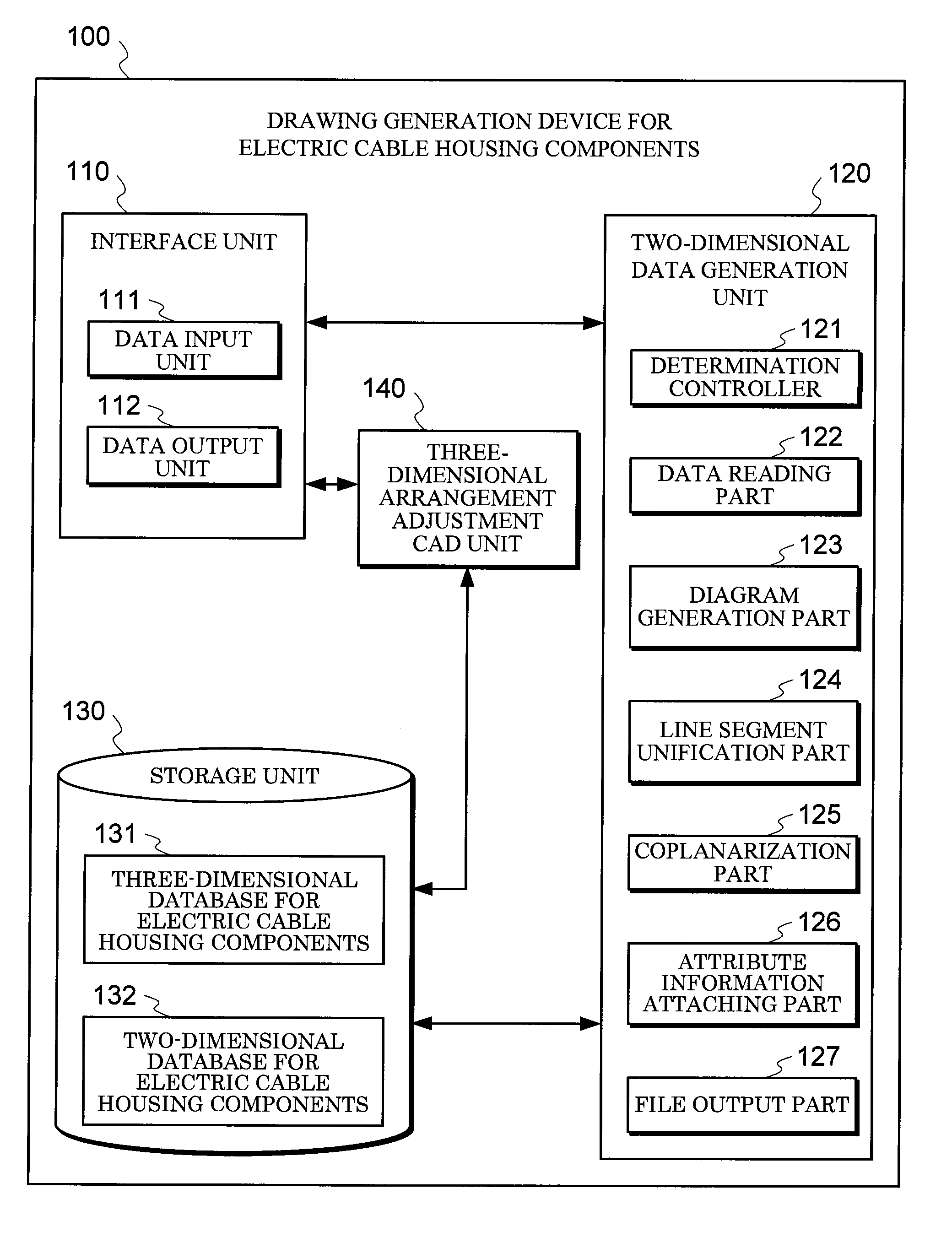
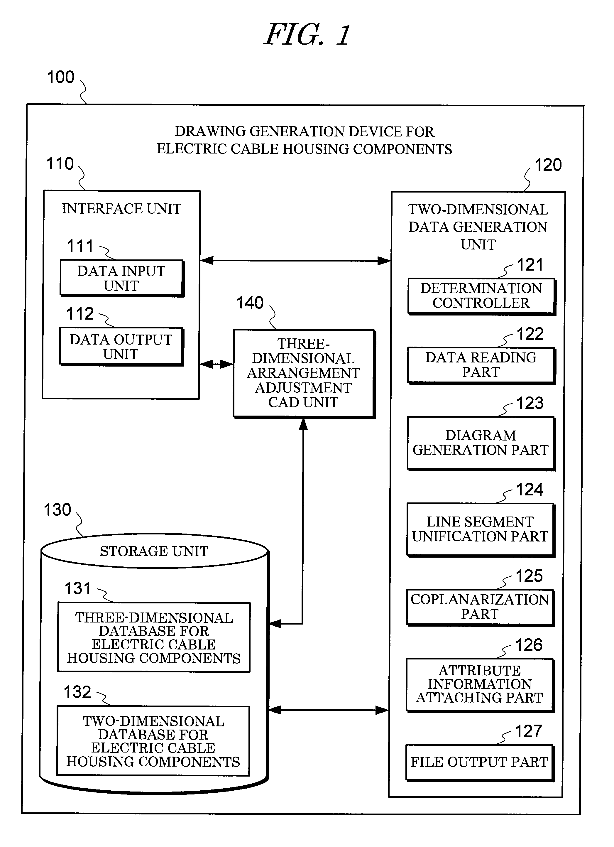
[0039]FIG. 1 is a block diagram showing a configuration of a drawing generation device 100 for electric cable housing components according to an embodiment of the present invention.

[0040]As shown in FIG. 1, the drawing generation device 100 for electric cable housing components according to this embodiment has an interface unit 110 for inputting / outputting various instructions and data, a two-dimensional data generation unit 120 for processing three-dimensional data of electric cable housing components and converting the three-dimensional data to two-dimensional data, a storage unit 130 for storing the three-dimensional data of the electric cable housing components that is input by the interface unit 110 and the two-dimensional data of the electric cable housin...


PUM


Abstract

To make possible using three-dimensional data of electric cable housing components to automatically generate and output a drawing that is simple and useful as two-dimensional data for clearly representing the relationship between upper and lower components. Determination controller 121 of two-dimensional data generation unit 120 converts three-dimensional data of electric cable housing components, which is read by the data reading part 122, into a line segment for each component by diagram generation part 123, and converts a contact part between components or a part where components partially overlap with each other, into an intersection point, to generate a diagram composed of the line segment and intersection point. Determination controller 121, by coplanarization part 125, shifts line segments of a plurality of components that overlap vertically on the diagram onto a single plane, and slides the line segments at a predetermined interval to represent the vertical overlap on the plane. Determination controller 121 outputs the generated two-dimensional data of the electric cable housing components from interface unit 110 in the form of file by file output part 127, and stores the data in the form of file in storage unit 130.

Description

BACKGROUND OF THE INVENTION[0001]1. Field of the Invention[0002]The present invention relates to a drawing generation device, method and program for electric cable housing components for converting three-dimensional data of electric cable housing components generated by a three-dimensional arrangement adjustment CAD into two-dimensional data by using a computer, and outputting the converted data in the form of drawing.[0003]2. Description of the Related Art[0004]Drawings of electric cable housing components of a thermal / nuclear / hydraulic plant are generated after arrangement planning is performed at the time of plant layout. Recently, this arrangement planning is recently performed by a three-dimensional arrangement adjustment CAD, for the reason of convenience of data input, expansion of the data to the downstream after the data input, and management of the data.[0005]When performing the arrangement planning on electric cable housing components, a designer arranges the electric cab...

Claims


Application Information

Patent Timeline
IPC IPC(8): G06T15/00
CPCG06F17/5081G06T2219/021G06T19/00G06T11/206G06F30/398G06F17/40
Inventor OKADA, YUUKIFUJII, SHINGOYABU, HIROKI
Owner KK TOSHIBA
Why Eureka
Try Eureka