
Tilt machining device and method

a technology of tilting machining and machining method, which is applied in the direction of work holders, manufacturing tools, metal-working machine components, etc., can solve the problems of inability to cut or grind a smooth angled surface not parallel to the work table surface of the machine or perpendicular to the spindle axis, excessive setup time and effort, and high manufacturing cost of “heavy plate system”

Active Publication Date: 2009-12-17
BLICK JOHN
View PDF6 Cites 30 Cited by
  • Summary
  • Abstract
  • Description
  • Claims
  • Application Information

AI Technical Summary

Benefits of technology

[0010]The support system and method of the present invention incredibly facilitates working flat objects at an angle on a three axis table, and also enables support of a complex shaped object to be worked, typically an object with a curved surface which will be processed on a five axis machine.
[0011]A vacuum support with a height adjustable bearing support can be laterally located on a working table using a spindle mounted locator with assistance by the metric capabilities of the spindle to achieve an x and y and z position automatically as a guide for setup personnel. This enables exact lateral and depth, two dimensional position location on a working table, along with height adjustment of a support, with or without vacuum operated hold down, on a conventional working table. This allows for location of the work piece in three axes with reference to the work table and machine spindle. The three axis positioning of the work support allows accurate location of the work piece with respect to the desired processing to be performed by either a three axis or a five axis machine or other multi axis machine.
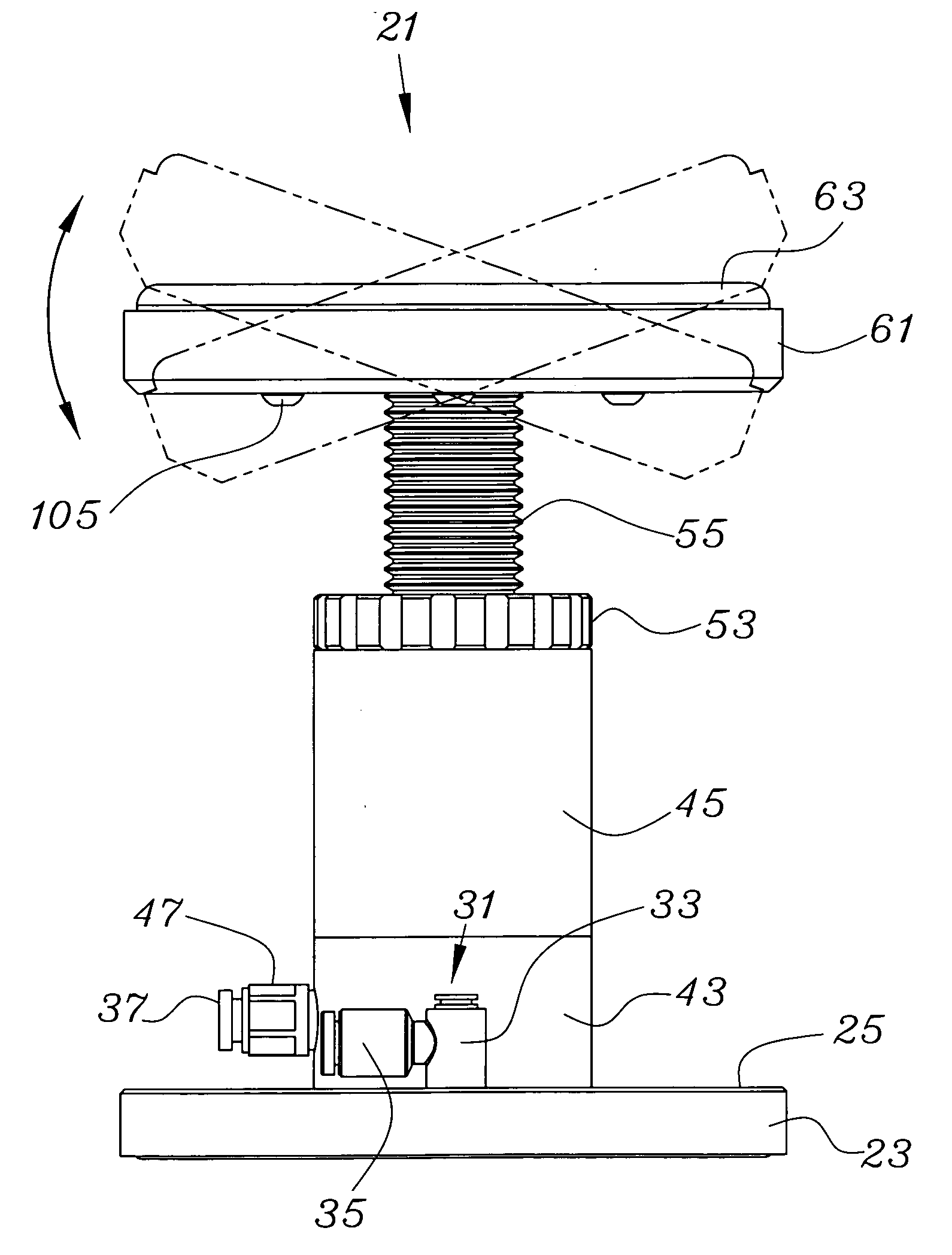
[0018]Because the upwardly directed sealing cup has a passive angular capability, sealing cups can be passively angularly displaced as the work piece is brought down onto the hold down supports. Activation of a vacuum between the upwardly directed sealing cup and the work piece acts to pull the work piece directly vertically down upon the main center bearing member, regardless of the angular position of the upwardly directed sealing cup thus stabilizing and forcefully securing the work piece. Depending upon the choice of material, the angular tilt of the upwardly directed sealing cup may be as much as fifty degrees or more of tilt in any direction, side, forward or back or any direction in between.

Problems solved by technology

Because the cutting head on the spindle on a three axis machine cannot tilt, an attempt to cut or grind a smooth angled surface not parallel to the machine work table surface or perpendicular to the spindle axis is not practically possible without the ability to tilt the work piece.
The “heavy plate system” is typically fabricated at considerable cost.
Further, each time a run of work pieces requiring a tilt is to be set up on a three axis machine, the setup time and effort is excessive.
The requirement of using a tilt plate and the extra effort for setup is extremely burdensome in terms of cost for the heavy plate, and the time required for setup.
Conventional hold downs will not work as conventional hold downs require a significant number of completely flat expanses on the bottom side of a work piece parallel to the work table so that a sufficient area of hold down vacuum can be applied, and this is almost never possible with a complex shape.
The costs of individual and specific custom made fixtures for each unique shape to be processed is prohibitive.

Method used


Image

  • Tilt machining device and method
  • Tilt machining device and method
  • Tilt machining device and method

Examples


Embodiment Construction

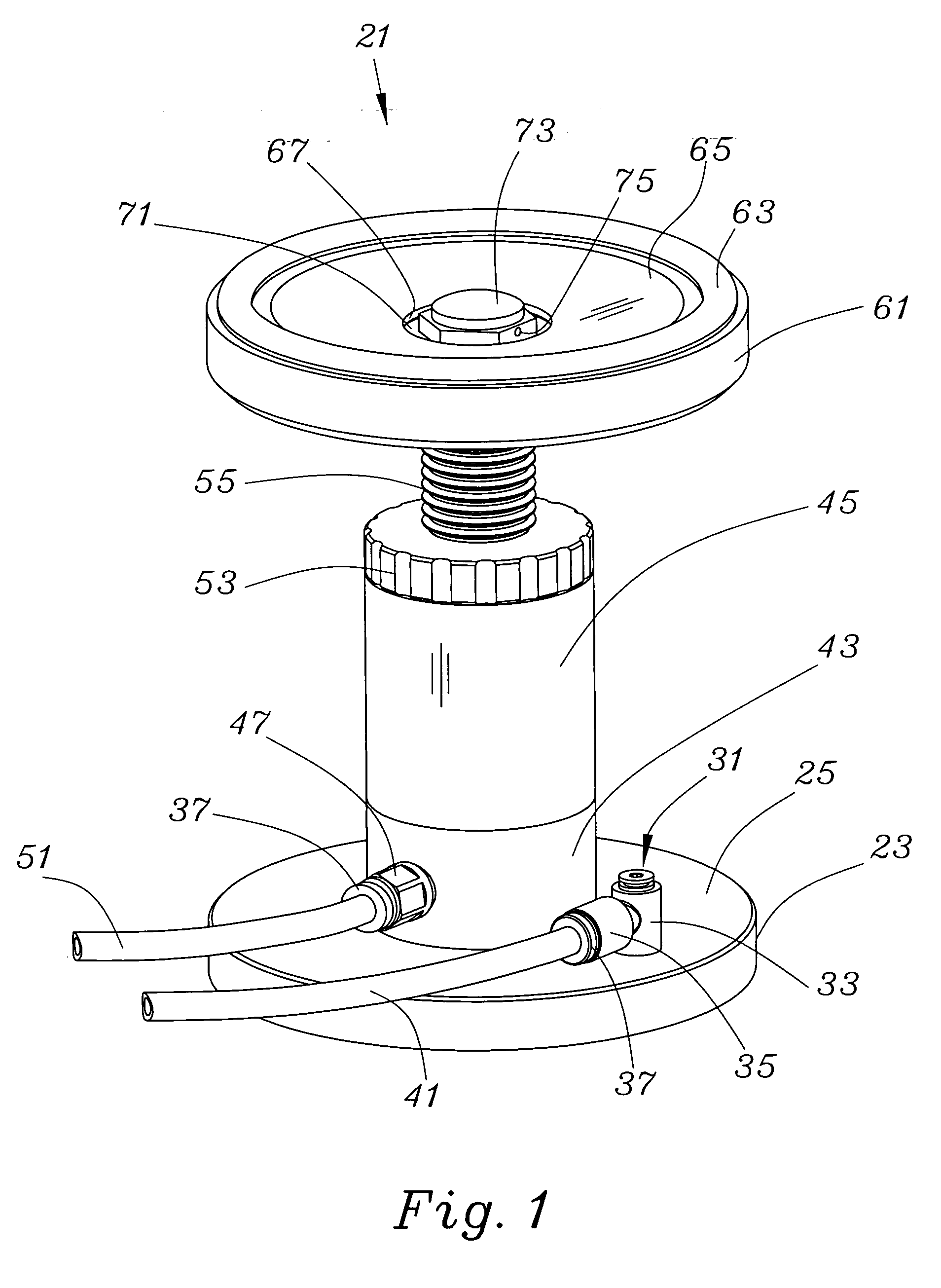
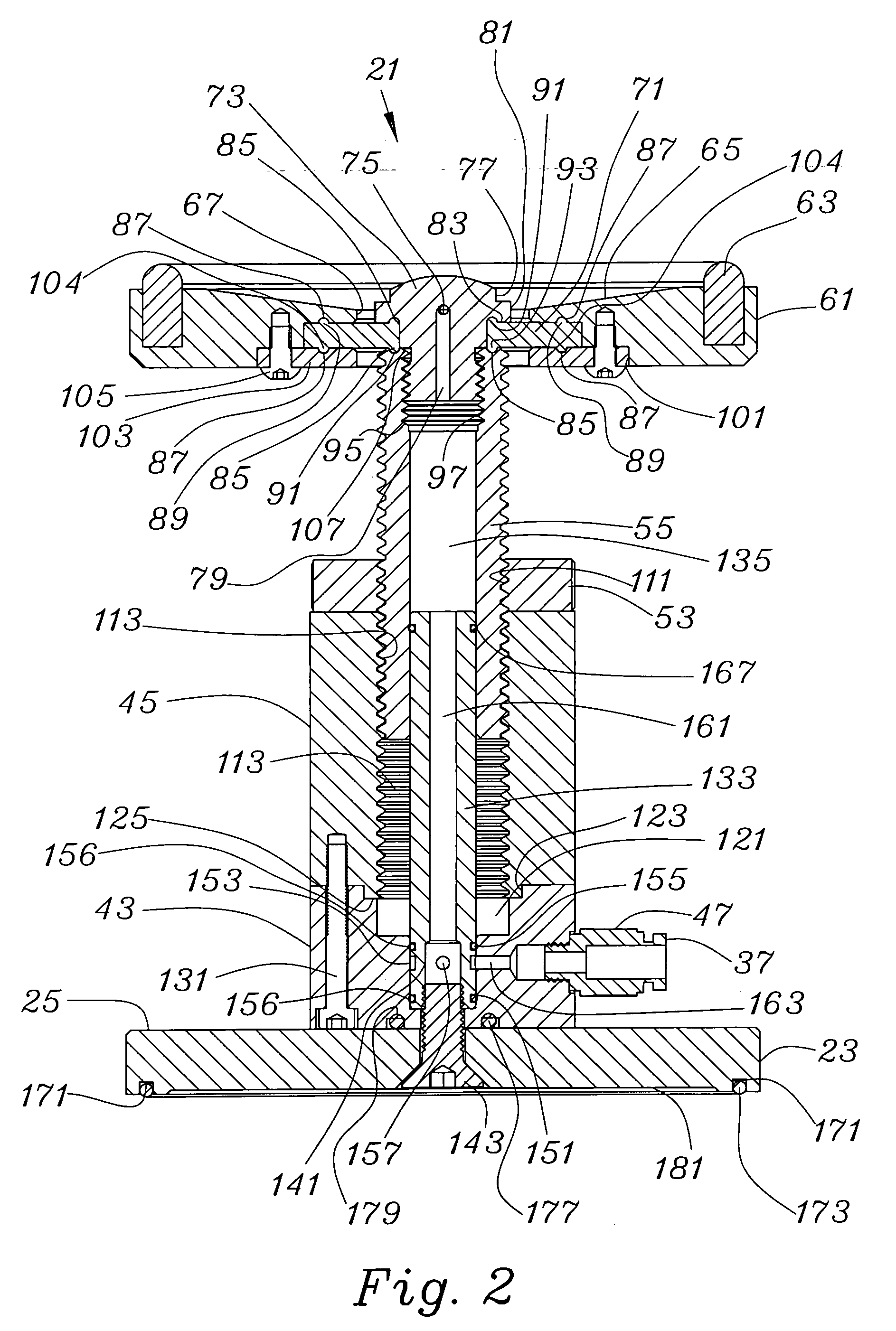
[0037]A description of the height adjustable jack screw support with angularly flexible hold down is seen in FIG. 1 as a hold down support 21. Hold down support 21 has a base 23 having an upper surface 25 supporting a base vacuum fitting 31. Base vacuum fitting 31 may be a pivoting base vacuum fitting 31 having a rotational housing 33 and a hose fitting assembly 35. The hose fitting assembly 35 may include a push ring 37 which is springingly held in the hose fitting assembly 35 to accept an insertable vacuum hose 41. This type of fitting assembly admits the end of the vacuum hose upon insertion through the push ring 37 and locks it in against a removal force. Pushing the push ring 37 toward the hose fitting assembly 35 unlocks the vacuum hose 41 and permits its removal. As will be shown, vacuum transmitted through the vacuum hose 41 is transmitted below the base 23 and locks the base 23, and indeed the entire hold down support 21, to a working table (not shown).

[0038]Also seen in FI...


PUM


Abstract

The support system and method enables exact and preferably machine assisted manual location and height placement of a vacuum operated hold down with rigid pre-set support on a conventional working table. A height adjustable jack screw support with angularly flexible hold down enables a holding support engaging the bottom of a work piece even where a lower surface of the work piece has an irregular shape due to the ability of the upper cup support to passively tilt to engage the work piece.

Description

FIELD OF THE INVENTION [0001]The present invention relates to improvements in the field of work holding devices for machining work. More specifically, the present invention relates to a device and method used to locate and secure both simple planar and complex compound shaped parts held in place by vacuum for the purpose of machine processing by computer numerical controlled milling machines typically used in the processing of sheet type materials by multi axis machines. The hold down system is used to accurately locate and secure sheet materials of various thickness, shape and composition to the working table surface of machines for processing.BACKGROUND OF THE INVENTION [0002]As was described in U.S. Pat. No. 5,562,276, issued on Oct. 8, 1996 to the inventor of the instant application and entitled “LOCATOR AND HOLD DOWN SYSTEM FOR A MACHINE” and which is incorporated by reference herein, a vacuum hold down system for a working table facilitated the location and positioning of stru...

Claims


Application Information

Patent Timeline
Patent Type & Authority Applications(United States)
IPC IPC(8): B25B5/16B25B11/00
CPCB23Q1/032B23Q1/46B23Q2230/002B23Q3/088B25B11/007
Inventor BLICK, JOHNWACHOLDER, DANIEL
Owner BLICK JOHN
Learn More