
Control system and apparatus for use with ultra-fast laser

a control system and laser technology, applied in the field of lasers, can solve the problems of insufficient reproducibility to be considered useful for analytical purposes, protein to char, selective chemical bond cleavage, etc., and achieve the effect of improving the encoding-decoding functionality of pulses, less expensive, and convenient setting up and us

Active Publication Date: 2011-07-05
BOARD OF TRUSTEES OPERATING MICHIGAN STATE UNIV
View PDF211 Cites 105 Cited by
  • Summary
  • Abstract
  • Description
  • Claims
  • Application Information

AI Technical Summary

Benefits of technology

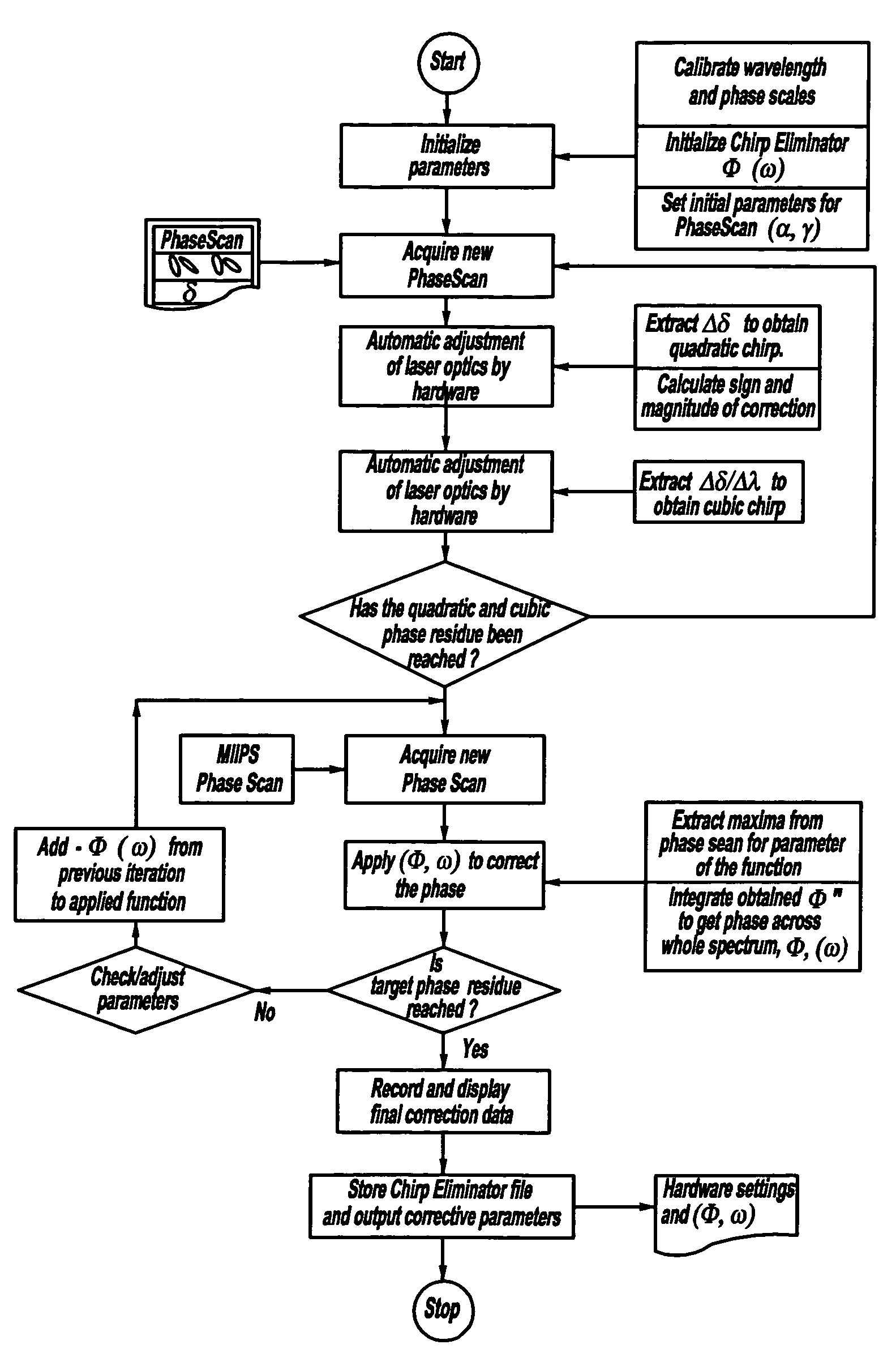
[0009]The present invention is advantageous over conventional constructions since the MIIPS aspect of the present invention employs a single beam which is capable of retrieving the magnitude and sign of second and third order phase modulation directly, without iteration or inversion procedures. Thus, the MIIPS system is much easier to set up and use, thereby creating a much less expensive system which is more accurate than conventional systems and methods. Furthermore, the MIIPS system of the present invention avoids the inaccuracies of the prior FROG, SPIDER and DOSPM methods due to environmental effects such as wind, vibrations and the like. The present invention MIIPS system utilizes the full bandwidth which works best with shorter laser beam pulses, such as femtosecond pulses; this is in contrast to the mere single frequency optimization of some convention devices. The present invention MIIPS system overcomes the traditional need for slower picosecond pulses for space-time correlation corrections due to inherent time delays created with prior synchronous use of multiple matched pulses, a first pump or fundamental pulse and another reference second harmonic pulse, caused by the pulse passage through a pulse shaping crystal. Additionally, the present invention advantageously uses one or more pre-stored comparison values for pulse signal decoding at a communications receiver such that the second reference pulse (and corresponding time delay correlation) are not necessary. The present invention also improves the encoding-decoding functionality of pulses by adding considerably more information to each pulse by obtaining the entire phase function directly from a phase scan. Intrapulse interferences of the present invention causes self separation (for example, inherent communication signal routing address differentiation) thereby allowing use of inexpensive receivers in an asynchronous manner, in other words, without the need for synchronous detection such as by traditional autocorrelation or interferometers.

Problems solved by technology

Similarly, the findings by Assion et al. had great scientific interest, but the results were not sufficiently reproducible to be considered useful for analytical purposes.
Direct laser excitation of the proteins with nanosecond lasers typically causes the proteins to char.
Laser induced, selective chemical bond cleavage has also been explored but with fairly limited success.
This method was not known to have been employed for a protein or MALDI process, and was not known to have been successfully used for any other atomic bonds in other molecules, especially not in a condensed phase.
However, the approach of Schmidt et al. does not modify and optimize the laser pulse shape or other laser properties to achieve limited bond cleavage.

Method used


Image

  • Control system and apparatus for use with ultra-fast laser
  • Control system and apparatus for use with ultra-fast laser
  • Control system and apparatus for use with ultra-fast laser

Examples


Embodiment Construction

Pulse Shaping System

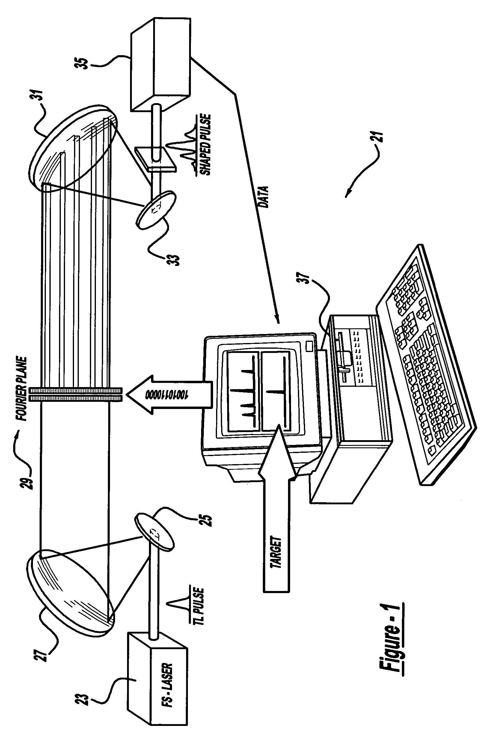
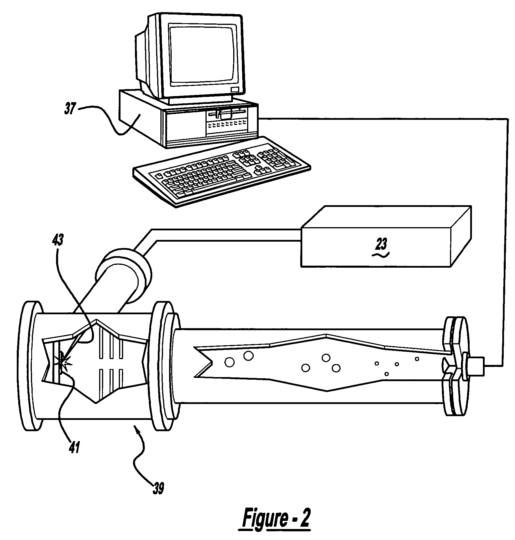
[0035]The first preferred embodiment of a laser system 21 using ultrashort laser pulses of the present invention is generally shown in FIG. 1. System 21 includes a femtosecond laser 23, an upstream grating 25, an upstream concave mirror 27, a spatial light modulator 29, a downstream concave mirror 31, a downstream grating 33, a detection device 35, and a personal computer 37. Personal computer 37 has a microprocessor based electrical control system, memory, an output screen, a data storage device, an input keyboard, and a removable disk. More specifically, the detection device is a spectrometer 39. Bursts or pulses of a laser beam 43 are emitted from laser 23, through the optics 25, 27, 31 and 33, as well as through the spatial light modulator 29 for detection and sensing by spectrometer 39 for further evaluation, analysis, comparison and subsequent control by personal computer 37.

[0036]The laser is preferably an ultra-short femtosecond laser that can deliver hig...


PUM


Abstract

A control system and apparatus for use with an ultra-fast laser is provided. In another aspect of the present invention, the apparatus includes a laser, pulse shaper, detection device and control system. A multiphoton intrapulse interference method is used to characterize the spectral phase of laser pulses and to compensate any distortions in an additional aspect of the present invention. In another aspect of the present invention, a system employs multiphoton intrapulse interference phase scan. Furthermore, another aspect of the present invention locates a pulse shaper and / or MIIPS unit between a laser oscillator and an output of a laser amplifier.

Description

CROSS-REFERENCE TO RELATED APPLICATIONS[0001]This application is a continuation-in-part of U.S. Ser. No. 10 / 265,211, filed Oct. 4, 2002 now U.S. Pat. No. 7,450,618, which is a Continuation-in-Part of PCT / US02 / 02548, filed Jan. 28, 2002, which claims priority to U.S. Provisional Application Ser. No. 60 / 265,133, filed Jan. 30, 2001; all of which are incorporated by reference herein.[0002]This application is a continuation-in-part of U.S. Ser. No. 10 / 628,874, filed Jul. 28, 2003 now U.S. Pat. No. 7,105,811, which is a Continuation of PCT / US02 / 02548, filed Jan. 28, 2002 which claims priority to U.S. Provisional Application Ser. No. 60 / 265,133, filed Jan. 30, 2001; all of which are incorporated by reference herein.[0003]This application is a continuation-in-part of U.S. Ser. No. 10 / 791,377, filed Mar. 2, 2004 now U.S. Pat. No. 7,609,731, which is a continuation-in-part of U.S. Ser. No. 10 / 265,211, filed Oct. 4, 2002 now U.S. Pat. No. 7,450,618, which is a Continuation-in-Part of PCT / US02...

Claims


Application Information

Patent Timeline
Patent Type & Authority Patents(United States)
IPC IPC(8): G01B9/02H01J49/16
CPCG01J11/00H01J49/164G01J3/00G01N21/00H01S3/0057H01S3/0014
Inventor DANTUS, MARCOS
Owner BOARD OF TRUSTEES OPERATING MICHIGAN STATE UNIV
Learn More