
Positionable gas injection nozzle assembly for an underwater pelletizing system

Active Publication Date: 2009-12-17
GALA INDUSTRIES INC
View PDF15 Cites 2 Cited by
  • Summary
  • Abstract
  • Description
  • Claims
  • Application Information

AI Technical Summary

Benefits of technology

[0009]In view of the foregoing, it is an object of the present invention to provide a positionable nozzle through which pressurized gas is introduced into the transport apparatus of an underwater pelletizer to increase the velocity of a pellet slurry being transported from a pelletizing process to and through a drying process while controlling the dynamics of the slurry flow through changes in the position of the nozzle.
[0015]Still a further object of the present invention is to provide a positionable nozzle through which pressurized gas is introduced that increases the velocity of a pellet slurry being transported from a pelletizing apparatus to and through a drying apparatus such that the internal heat of the pellets is retained to facilitate drying of the pellets such that the moisture content of the pellets leaving the drying apparatus is less than approximately 1.0% by weight, more preferably less than 0.5% by weight, and most preferably less than 0.25% by weight.
[0016]An additional object of the present invention is to provide a positionable nozzle through which pressurized gas is introduced to increase the velocity of a pellet slurry being transported from a pelletizing apparatus to and through a drying apparatus such that the internal heat of the pellets is retained to facilitate both drying and crystallization of the pellets.
[0017]A further object of the present invention is to provide a positionable nozzle in accordance with the preceding object through which pressurized gas is introduced that increases the velocity of a pellet slurry being transported from a pelletizing apparatus to and through a drying apparatus such that the pellets leaving the drying apparatus are crystallized at least 20% by weight, more preferably at least 30% by weight, and most preferably at least 40% by weight.
[0018]Yet a further object of the present invention is to provide a positionable nozzle that can be retracted at least partially to prevent pellet hang-up during start-up of the pelletization process, and that can be moved forward to expedite the flow of the pellet slurry into and through the transport pipe and to facilitate the aspiration of the transport liquid away from the pellets as they move through the transport pipe.
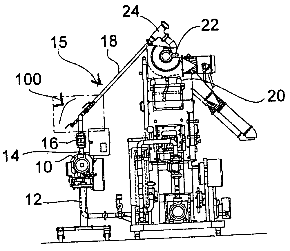
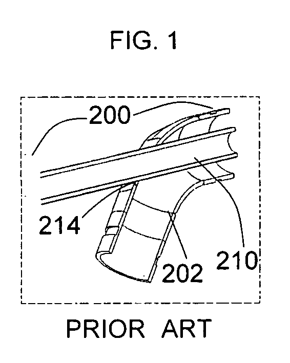
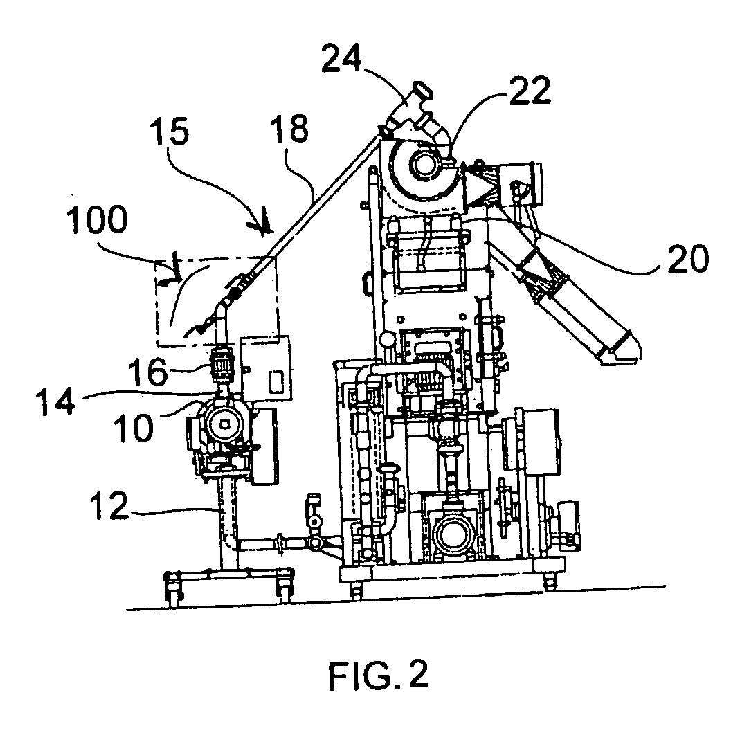
[0020]In view of these and other objects, the present invention is directed to an injecting device for use with an underwater pelletizer apparatus that extrudes and cuts polymer strands into pellets which are conveyed as a water and pellet slurry through transport piping to a centrifugal dryer. The injecting device includes a positionable nozzle assembly having an adjustable injection position to introduce a pellet speed expediter into the water and pellet slurry to increase a velocity of the pellet slurry to and through the dryer such that more internal heat of the pellets is retained. The nozzle assembly is adjustable between a fully inserted position in which a nozzle tube of the assembly is positioned forwardly within the transport piping and a fully retracted position in which the nozzle tube is withdrawn from the transport piping to provide wholly unobstructed flow of the slurry through the piping. Preferably, the positionable nozzle assembly is configured so that the nozzle tube can be positioned manually or mechanically, at various intermediate positions between the fully inserted forward position and the fully retracted position.

Problems solved by technology

The reduced retention time also results in more of the internal heat of the pellets formed being retained, and thus reduces the moisture available for uptake by the pellets.
As an example, agglomerates of pellets can form when “drooling”, excessive flow of molten material through the die holes, occurs at the die plate, thus creating an undesirably large pellet.
Pellets of desirable size can create a problem as well.
Sticky pellets, or pellets that are still soft, that come into contact with the nozzle can be “smashed” and stick to the nozzle due to their stickiness and the velocities at which they are traveling.
Eventually the mass of pellets can become large enough to disrupt the flow of transport liquid and pellets through the transport pipe.

Method used


Image

  • Positionable gas injection nozzle assembly for an underwater pelletizing system
  • Positionable gas injection nozzle assembly for an underwater pelletizing system
  • Positionable gas injection nozzle assembly for an underwater pelletizing system

Examples


Embodiment Construction

[0034]Although preferred embodiments of the invention are explained in detail, it is to be understood that other embodiments are possible. Accordingly, it is not intended that the invention is to be limited in its scope to the details of constructions, and arrangement of components set forth in the following description or illustrated in the drawings. The invention is capable of other embodiments and of being or carried out in various ways. Also, in describing preferred embodiments, specific terminology will be resorted to for the sake of clarity. It is to be understood that each specific term includes all technical equivalents which operate in a similar manner to accomplish a similar purpose. Where possible, components of the drawings that are alike are identified by the same reference numbers.

[0035]The positionable nozzle assembly according to the present invention helps to enhance the crystallization of various polymeric materials and also facilitates drying of those and other ma...


PUM

PropertyMeasurementUnit
Percent by massaaaaaaaaaa

Abstract

A positionable gas nozzle assembly for injecting and directing pressurized air or other gas having an inert nature into a pellet slurry so as to increase the velocity of the slurry from a pelletizer to and through a dryer. The variably positionable nozzle can be inserted, retracted and / or intermediately positioned to facilitate start-up of the pelletization process, reduce or eliminate pellet hang-up points, maximize and optimize the velocity of the pellet slurry throughput, and to adjust the aspiration level of the pellet slurry such that the internal heat of the pellets is retained for improved degrees of crystallization and / or drying.

Description

BACKGROUND OF THE INVENTION[0001]1. Field of the Invention[0002]The present invention relates generally to underwater pelletizing systems and, more particularly, to a gas injection nozzle for use with such systems.[0003]2. Description of Related Art[0004]Those skilled in the art have found it beneficial, and sometimes necessary, to produce pellets that crystallize, either partially or fully. To help achieve that crystallization, the assignee of the present invention has disclosed the use of a nozzle through which pressurized air or other gas can be injected into the pellet slurry to help decrease the retention time of the pellets in the transportation liquid between the upstream pelletization process and the downstream drying and subsequent processes in U.S. Pat. No. 7,157,032; U.S. Patent Application Publication Nos. 2005 / 0110182 and 2007 / 0132134; World Patent Application Publication Nos. WO 2005 / 051623, and WO 2006 / 127698, all of which are owned by the current assignee of the pres...

Claims


Application Information

Patent Timeline
IPC IPC(8): B29B9/02
CPCB29B9/16B29B9/06B29B9/065
Inventor MANN, ROBERT G.SIMMONS, CHARLES W.RYAN, ROBERT A.
Owner GALA INDUSTRIES INC
Learn More