Orb Launching Device

Active Publication Date: 2016-08-18
KMA CONCEPTS
View PDF0 Cites 2 Cited by
  • Summary
  • Abstract
  • Description
  • Claims
  • Application Information

AI Technical Summary

Benefits of technology

The present invention is a device for launching toys. It consists of a handle, barrel, muzzle, trigger, cocking shaft and cocking handle. The device uses a spring-loaded shaft to launch an orb. The launching mechanism rotates the orb, which stabilizes it in flight, allowing it to achieve higher velocities and longer journeys. This method of launching is effective even with a flexible orb material.

Problems solved by technology

The novel method of launching the orb imparts rotation on a flexible orb, which can be difficult.

Method used


Image

  • Orb Launching Device
  • Orb Launching Device
  • Orb Launching Device

Examples


Embodiment Construction

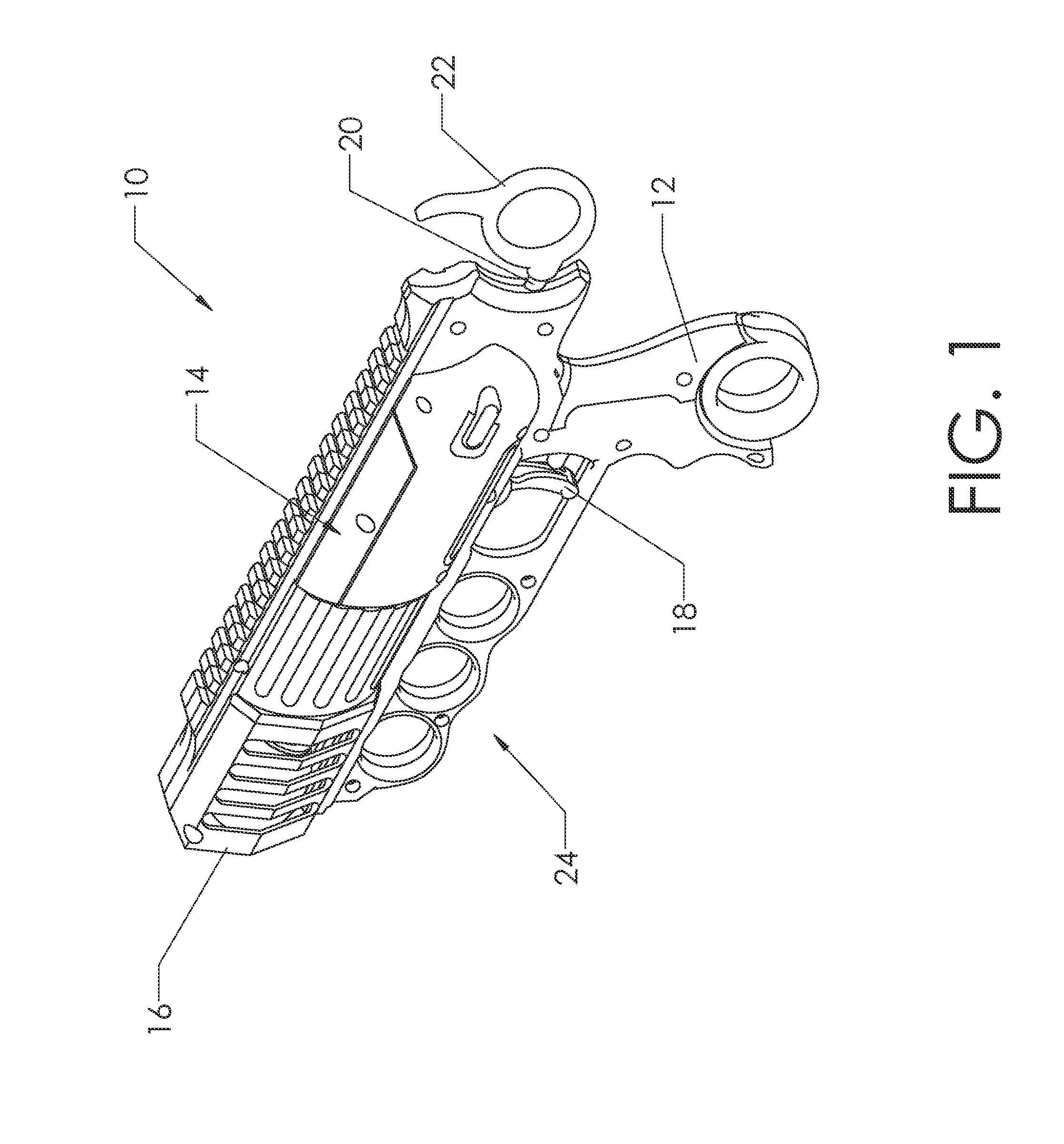
[0056]The present invention provides a projectile launching device for use in target practice and other games played using a device which launches soft projectiles. FIG. 1 shows a preferred embodiment. Preferably, orb launching device 10 includes launcher handle 12, chassis 14, muzzle 16, trigger 18, cocking shaft 20, and cocking handle 22. Cocking shaft 20 is configured to slide in and out of chassis 14. In addition, orb launching device 10 includes resistance grip 24. Resistance grip 24 preferably allows the user to maintain a sufficient grip while pulling cocking handle 22 back in order to cock orb launching device 10. The reader will note that resistance grip 24 is shown as a multi-finger grip, but should not be limited to this. Resistance grip 24 could just as easily be a handle or other type of grip similar to launcher handle 12 or like that on a rifle.

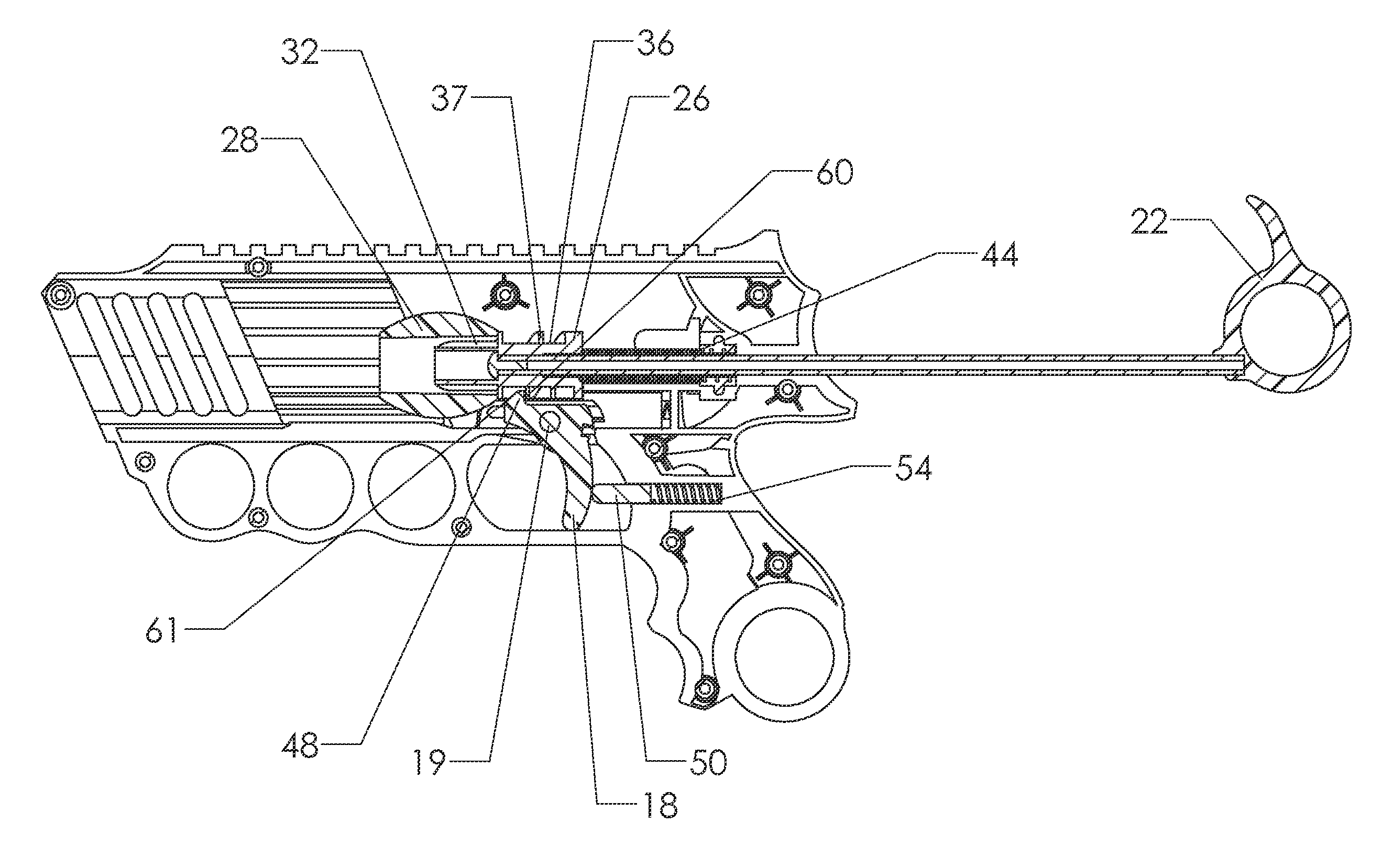
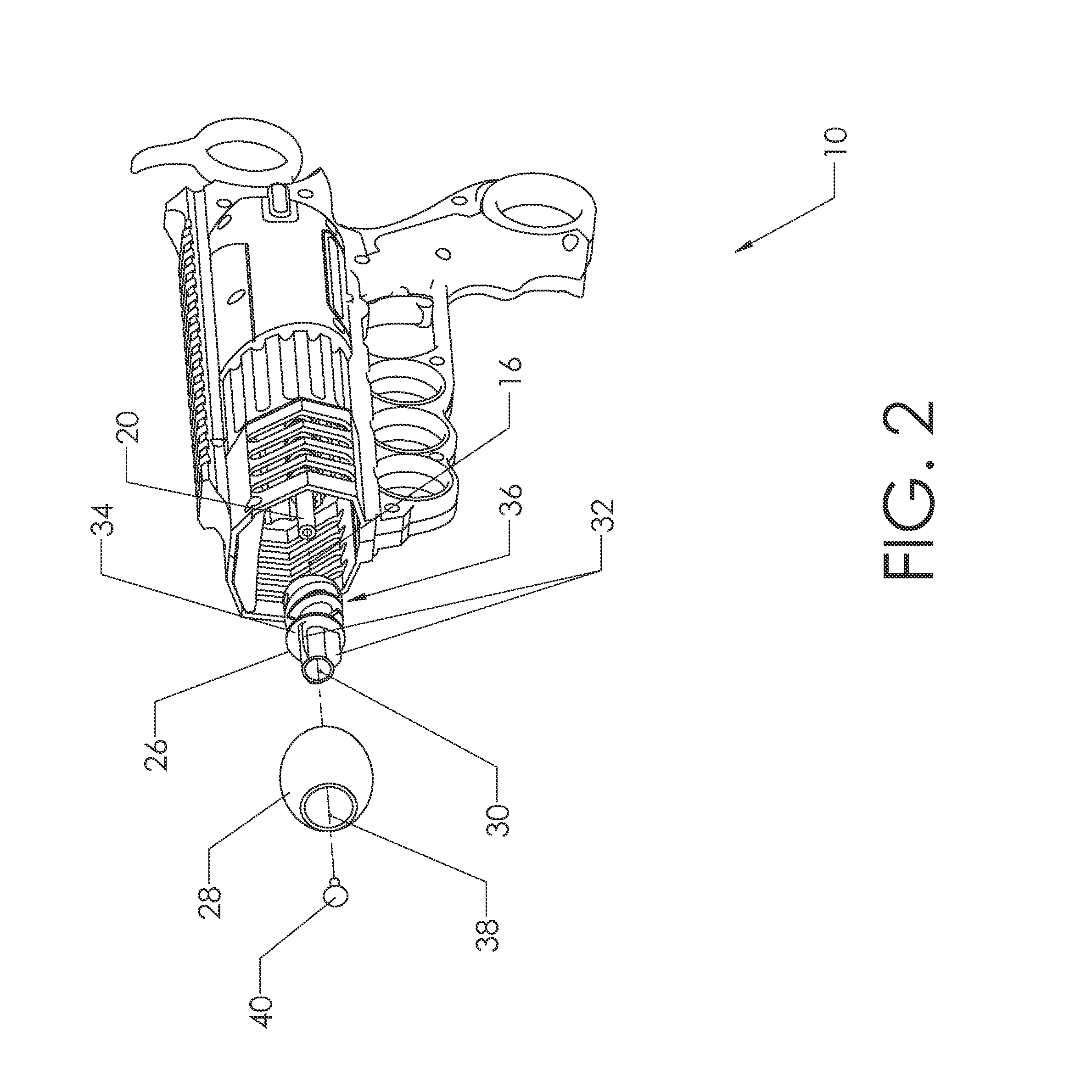
[0057]FIG. 2 shows orb launching device 10 partially exploded in order to show details of the firing mechanism of orb launchin...


PUM


Abstract

A toy projectile launching device. The device preferably includes a handle, barrel, muzzle, trigger, cocking shaft, and cocking handle. The device uses a spring loaded shaft in order to launch an orb. In addition, the launching mechanism of the device imparts rotation upon the orb, which stabilizes the orb in flight—thereby achieving an increase in sustained velocity and an increase in the distance traveled.

Description

BACKGROUND OF THE INVENTION[0001]1. Field of the Invention[0002]This invention relates to the field of toy projectile launching devices. More specifically, the present invention comprises a projectile launcher which launches a spin-stabilized orb.[0003]2. Description of the Related Art[0004]Toy projectile launchers are commonly used by children for target practice and for war-type games. Projectile launchers come in many forms, such as slingshots, bows, gun-type devices, and a multitude of other devices. Of course, each of those devices typically uses a different type of projectile. For example, a bow uses an arrow as a projectile and a slingshot launches a small round pellet, rock, or water balloon.[0005]In addition, particular launchers are designed to launch different projectiles. As an example, the reader will realize that gun-type projectile launchers are often used to launch a variety of projectiles, including bullets, spherical pellets, cylindrical pellets, and many others. O...

Claims


Application Information

Patent Timeline
IPC IPC(8): F41B7/00F41B7/08
CPCF41B7/08F41B7/003F42B10/26
Inventor MITCHELL, JEFFREY R.
Owner KMA CONCEPTS
Why Eureka
Try Eureka