Valve train for internal combustion engine

Inactive Publication Date: 2009-12-17
HONDA MOTOR CO LTD
View PDF0 Cites 23 Cited by
  • Summary
  • Abstract
  • Description
  • Claims
  • Application Information

AI Technical Summary

Benefits of technology

[0008]The present invention has been made in view of the foregoing problems and it is therefore an object of the present invention to suppress the fluctuation of the torque applied to a camshaft included in a valve train for an internal combustion engine by a torque reducing mechanism, to suppress increase in the weight of the camshaft caused by the torque reducing mechanism, and to suppress increase in the size of the internal combustion engine ensuring a necessary supporting rigidity for supporting a counterforce applying mechanism included in the torque reducing mechanism.
[0009]Another object of the present invention is to enhance torque fluctuation suppressing effect by achieving a simple setting of a proper counter torque for suppressing the fluctuation of torque, to suppress increase in the size of an internal combustion engine resulting from the use of a torque reducing mechanism by increasing the degree of freedom of determining the position of a counterforce applying mechanism included in the torque reducing mechanism, and to reduce the size of the internal combustion engine by properly determining the position of an arm.
[0010]A further object of the present invention is to increase the degree of freedom of determining the position of a lever included in a torque reducing mechanism with respect to an axial direction, to arrange the lever and a pressing device included in the torque reducing mechanism in a compact arrangement with respect to a direction perpendicular to the camshaft axial direction as viewed in a direction parallel to the cylinder axis, to improve the effect of sealing the joint between a cylinder head and a cylinder block by the pressing device included in the torque reducing mechanism, to increase the degree of freedom of arranging an intake camshaft torque reducing mechanism and an exhaust camshaft torque reducing mechanism in a space between an intake camshaft and an exhaust camshaft, and to reduce loss in driving torque for rotating the camshafts caused by the torque reducing mechanisms.

Problems solved by technology

In such a case the rigidity of the camshaft needs to be enhanced still further, which increases the weight of the camshaft still further.
Therefore, the degree of freedom of arrangement of the counterforce applying mechanism is small and, in some cases, the size of the internal combustion engine in the direction of the pressing force increases.
When the counterforce applying mechanism of the torque reducing mechanism is in contact with the counteraction cam when the camshaft is at an angular position where the torque fluctuates in a narrow range, friction between the counterforce applying mechanism and the counteraction cam increases loss in the torque for rotating the camshaft

Method used


Image

  • Valve train for internal combustion engine
  • Valve train for internal combustion engine
  • Valve train for internal combustion engine

Examples


first embodiment

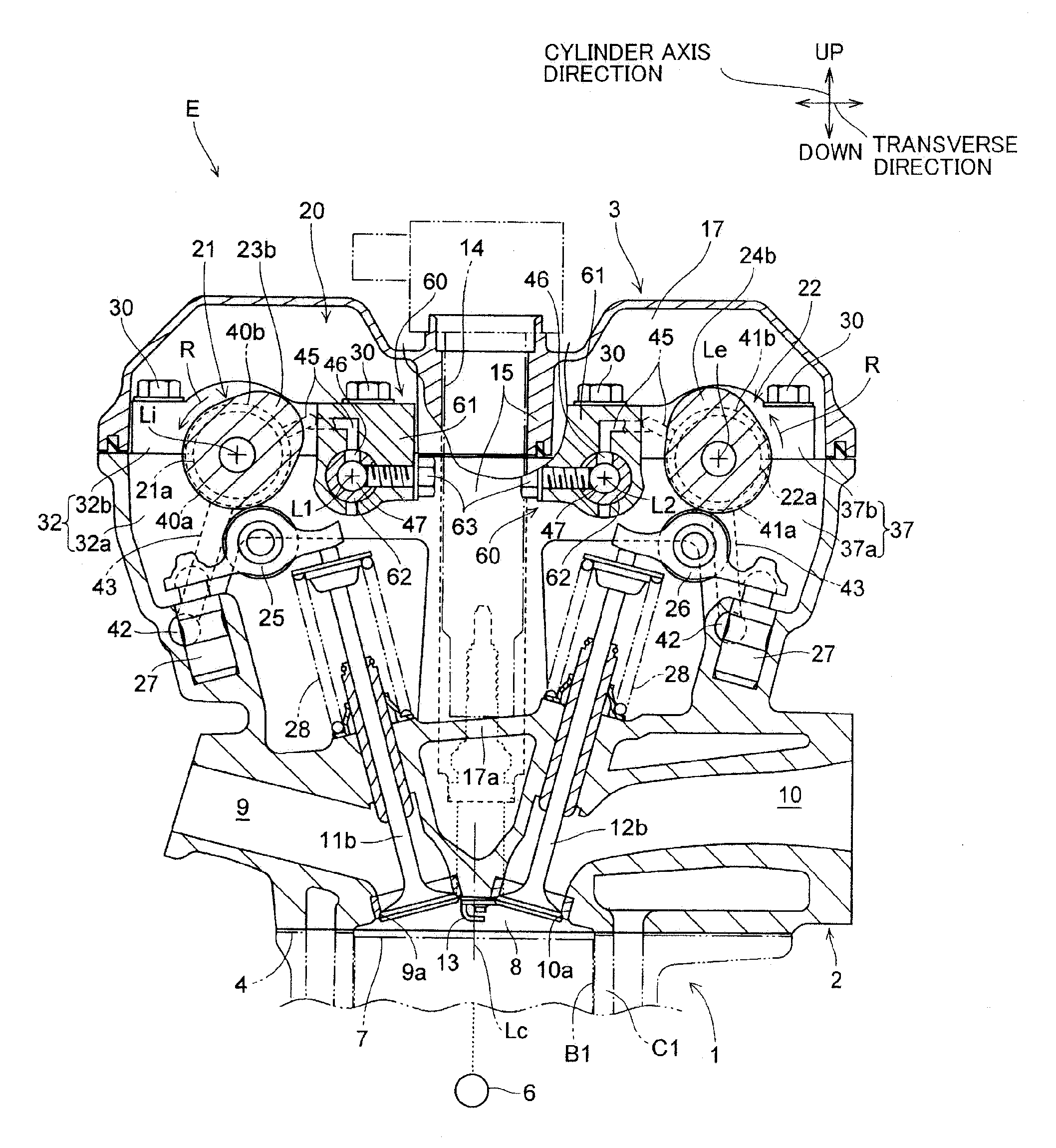
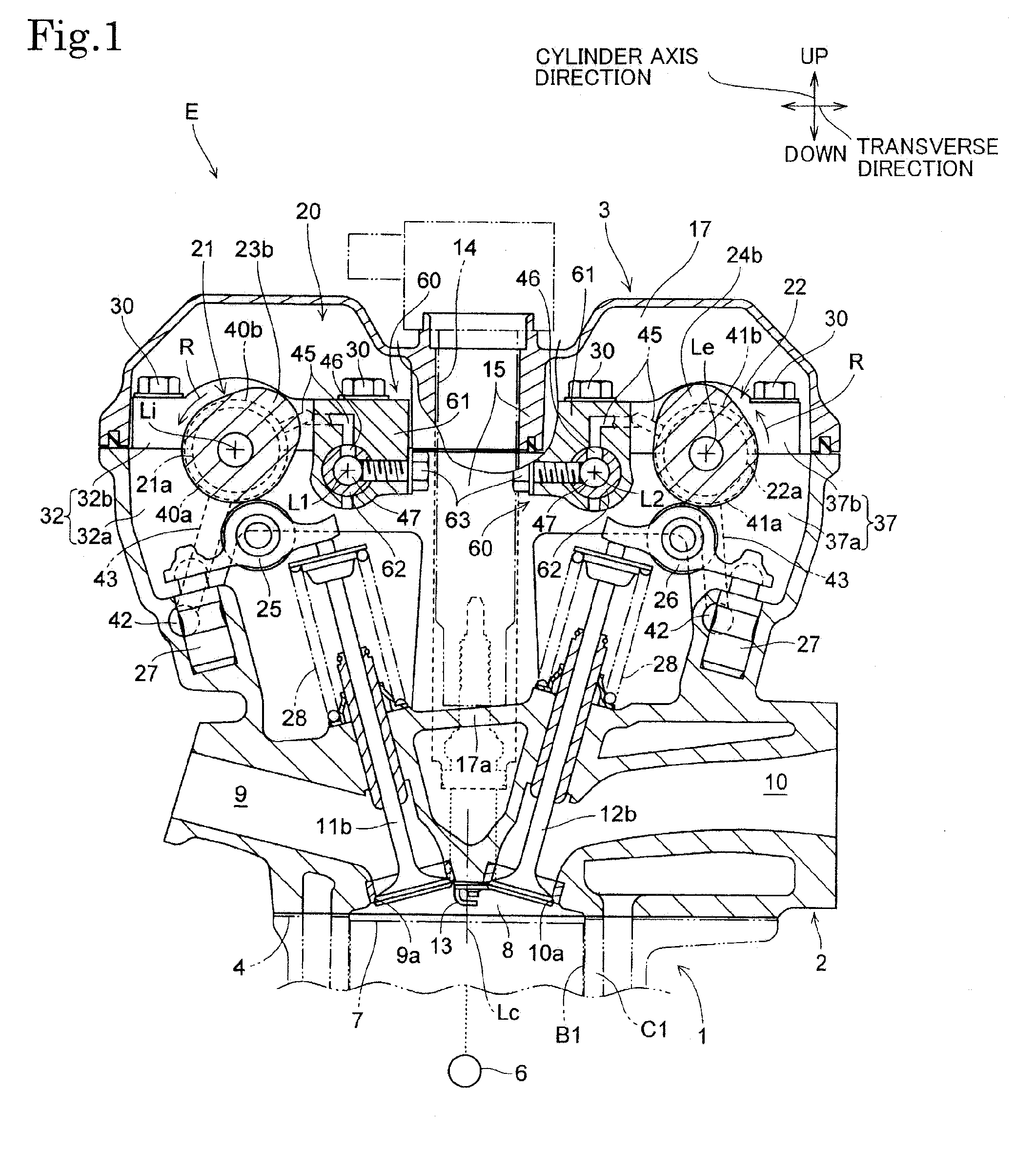
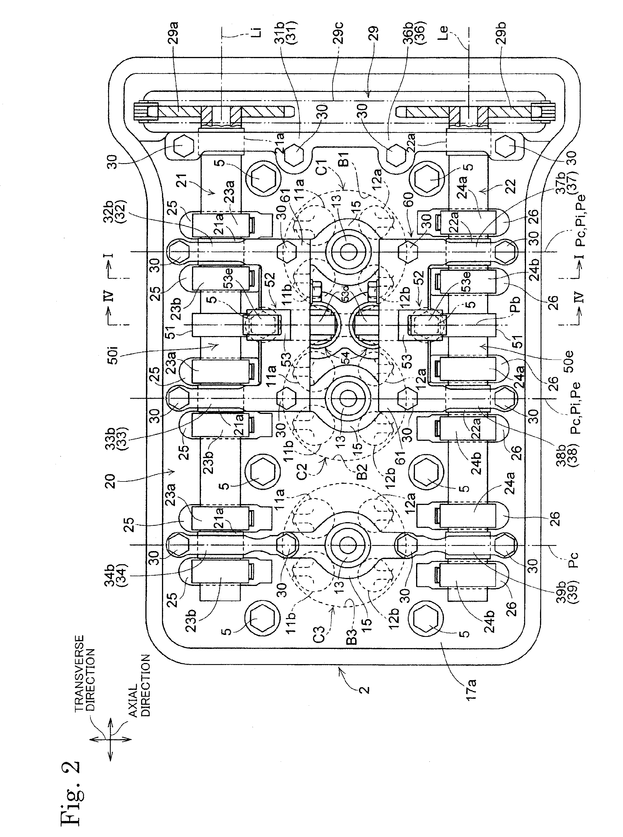
[0048]FIGS. 1 to 6 are views of assistance in explaining a valve train 20 in the present invention.

[0049]Referring to FIGS. 1 and 2, an internal combustion engine E provided with the valve train 20 of the present invention is a multiple-cylinder four-cycle internal combustion engine. The internal combustion engine E has an engine body including a cylinder block 1 provided with, for example, three cylinders C1 to C3 arranged in a line along an axial direction parallel to the axes of camshafts 21 and 22, a cylinder head 2 joined to the upper end of the cylinder block 1 with a head gasket 4 held between the cylinder block 1 and the cylinder head 2, and a head cover 3 joined to the upper end of the cylinder head 2.

[0050]In the following description, a ‘vertical direction’ is a cylinder-axis direction parallel to the axes Lc of the cylinders C1 to C3, an ‘axial direction’ is a direction parallel to the respective center axes Li and Le of the camshafts 21 and 22, and a ‘transverse directi...

second embodiment

[0119]The phase control mechanism 91, namely, a first phase control mechanism turns the outer camshaft 121. The phase control mechanism 92, namely, a second phase control mechanism, turns the inner camshaft 221. In the second embodiment, the phase control mechanisms 91 and 92 having the same basic construction are generally known hydraulic phase control mechanisms.

[0120]The first phase control mechanism 91 combined with the outer camshaft 121 has a body 91a integrally provided with a cam sprocket 29a, and a rotating member 91b received in the body 91a so as to be turnable relative to the body 91a and connected to the outer camshaft 121 so as to be rotatable together with the outer camshaft 121. The second phase control mechanism 92 combined with the inner camshaft 221 has a body 92a that rotates together with the outer camshaft 121, and a rotating member 92b combined with the body 92a so as to be turnable relative to the body 92a.

[0121]An ignition advance chamber and an ignition de...

third embodiment

[0165]In the third embodiment, most part of the pressing member 54a, the compression coil spring 54c, the roller 53d and the holding protrusion 70 with respect to the transverse direction may be disposed opposite to the counteraction cam 51 with respect to the center plane Pn of the internal combustion engine E. When the pressing member 54a, the compression coil spring 54c, the roller 53d and the holding protrusion 70 are thus arranged, the distance between the support shaft 62 and the roller 53d with respect to the transverse direction is increased and the lever ratio of the lever 53 can be diminished still further; that is, the same counter torque can be produced by a force lower than the force Fa or an increased counter torque can be produced by the same force Fa.

[0166]The camshafts may be supported in rolling bearings or sliding bearings on the camshaft supports.

[0167]The counteraction cam and the camshaft may be separately made and the counteraction cam may be mounted on the ca...


PUM

PropertyMeasurementUnit
Forceaaaaaaaaaa
Torqueaaaaaaaaaa

Abstract

A valve train of an internal combustion engine is provided with a plurality of camshaft supports arranged on a support member of the engine, and a camshaft is supported on the camshaft supports. The camshaft has valve operating cams thereon for opening and closing engine valves of engine. A torque reducing mechanism is provided to apply a counter torque to the camshaft to suppress torque fluctuation of the camshaft caused by reaction forces applied to the cams by the engine valves. The torque reducing mechanism has a rotating member that rotates together with the camshaft, and a counterforce applying member for applying a counterforce to the rotating member to apply a counter torque to the camshaft. The counterforce applying member is supported on a connecting member connecting adjacent ones of the camshaft supports. The torque reducing mechanism suppresses torque fluctuation of the camshaft, suppresses increase in the weight of the camshaft, and suppresses increase in the size of the engine, ensuring a necessary supporting rigidity for supporting a counterforce applying mechanism included in the torque reducing mechanism.

Description

BACKGROUND OF THE INVENTION[0001]1. Technical Field[0002]The present invention relates to a valve train for opening and closing engine valves, namely, intake valves or exhaust valves, of an internal combustion engine. More concretely, the present invention relates to a valve train provided with a torque reducing mechanism for suppressing the fluctuation of torque applied to a camshaft provided with valve-operating cams for opening and closing the valves of an engine.[0003]2. Description of the Related Art[0004]A valve train for an internal combustion engine, disclosed in, for example, JP 62-48105 B includes a camshaft provided with cams for opening and closing valves, and a torque reducing mechanism for applying a counter torque for suppressing torque fluctuation resulting from forces applied to the cams by the valves to the camshaft. The torque reducing mechanism includes a rotating member, such as a counteraction cam which rotates together with the camshaft, and a counterforce app...

Claims


Application Information

Patent Timeline
IPC IPC(8): F01L1/04
CPCF01L1/047Y10T29/49293F01L1/18F01L1/185F01L1/26F01L1/267F01L1/344F01L1/3442F01L2001/0473F01L2001/0478F01L2001/0537F01L2001/34469F01L2001/34489F01L2105/00F01L1/08F01L2305/00
Inventor TASHIRO, MASAHIKO
Owner HONDA MOTOR CO LTD
Why Eureka
Try Eureka