
Holder for holding a tooth on a body of a cutting blade or grinding drum for cutting or grinding rock or hard earth formations

a technology of cutting blades and holders, which is applied in the direction of cutting machines, earth drilling and mining, construction, etc., can solve the problems of detriment to structural strength, and achieve the effect of improving resistance to wear, repairing the cutting blades or grinding drums having holders with sleeves, and significant practical advantages

Inactive Publication Date: 2009-12-10
ROCK SAW HLDG
View PDF7 Cites 14 Cited by
  • Summary
  • Abstract
  • Description
  • Claims
  • Application Information

AI Technical Summary

Benefits of technology

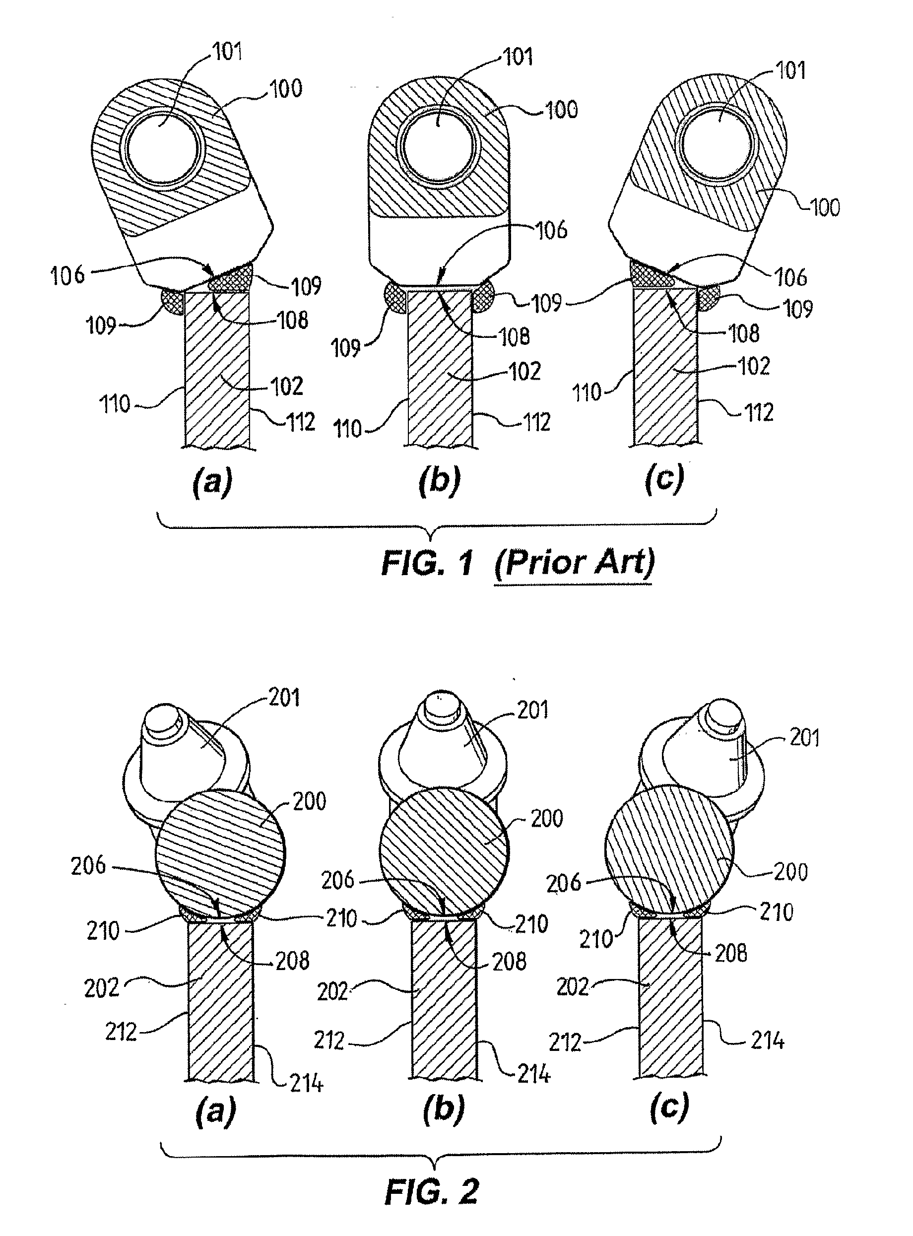
[0010]In contrast, the holder according to the first aspect of the present invention has a base surface that is profiled so that a region defined between the base surface and the attachment surface is, for at least one of the plurality of different orientations, smaller than a region that would be defined if the or each surface would have a flat shape. For example, the base surface may have a convexly-curved cross-sectional shape. If such a holder is positioned in a tilted orientation, the gap between the base surface and the attachment surface is smaller compared with a gap that would be formed using a prior art holder. Consequently a reduced amount of welding material is required and the structural stability increased. Further, shrinkage of the welding material during cooling of the welding material is less problematic.
[0011]The base surface typically has rounded and / or angled surface portions and in one specific embodiment the entire base surface is curved. The base surface typically also has a relatively long extension in a direction along the attachment surface of the body which increases the welding area and improves bonding strength. For fabrication of the cutting blade or grinding drum the holder may be rotated on the attachment surface, typically by an angle between 0° and 260°, and secured in a position in which the respective tooth projects in the desired direction relative to the body. In one specific embodiment of the present invention the entire holder has a circular cross-sectional shape.
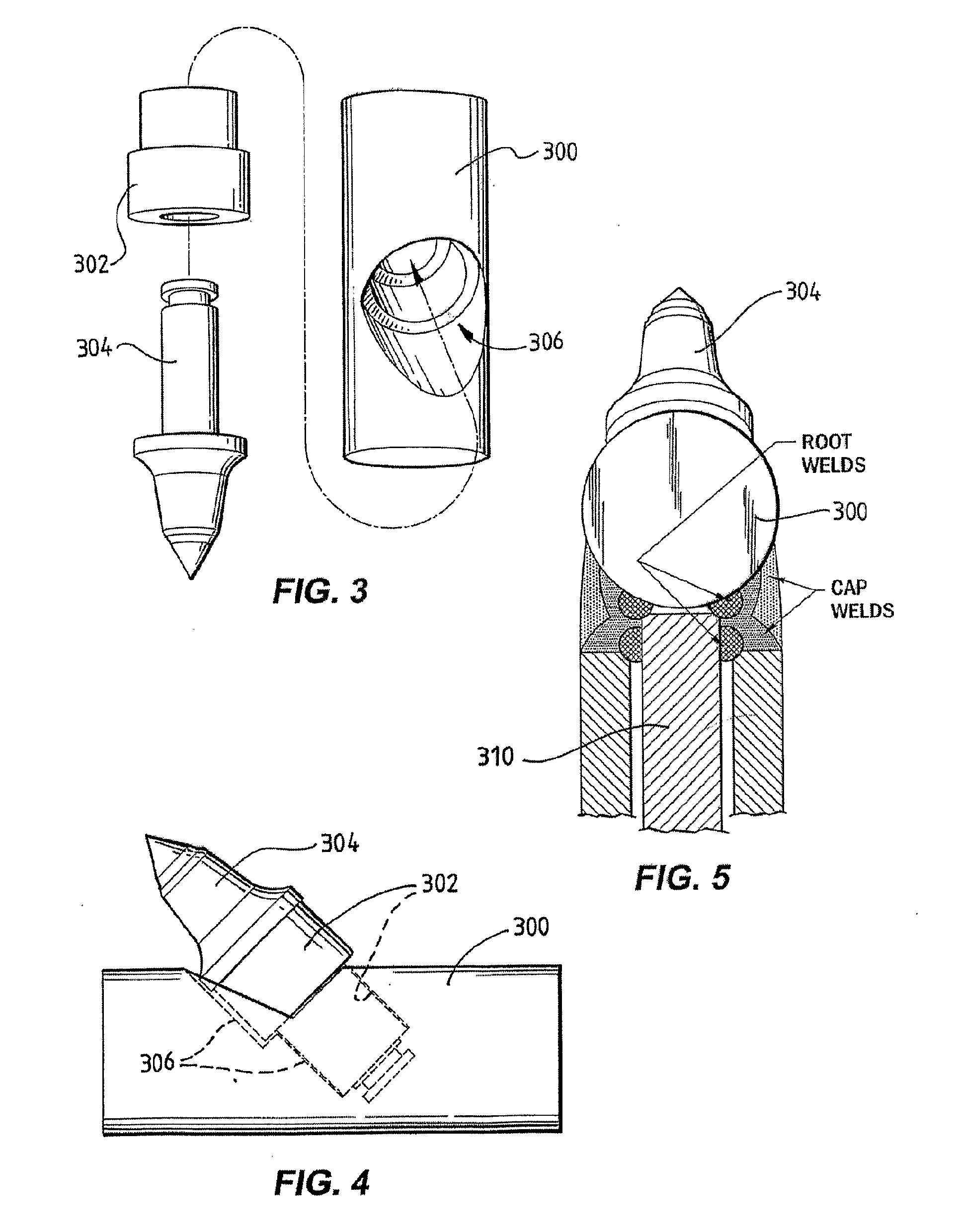
[0013]The portion for holding the tooth may also be arranged for receiving the tooth via a sleeve or the like. In one specific embodiment of the present invention the holder comprises the sleeve which is securable in the portion for receiving the tooth by welding, by a frictional fit of tapered portions or by a pin such as a role pin. In this embodiment the portion for holding the tooth is arranged to receive a socket portion of the tooth via the sleeve. This embodiment has significant practical advantages. A grinding drum or cutting blade typically comprises a plurality of teeth with holders and the teeth projecting from the body receive significant impact during cutting or grind actions which may result in wear of external portions of the holders and also of the portions which hold the teeth in position. Typically the teeth are held in position in circular bores which may become oval due to the impact associated with the cutting action. In this case the teeth are not held in their preferred position and it will be necessary to repair the cutting blade. Repairing of the cutting blade or grinding drum having the holders with the sleeves according to the specific embodiment of the present invention is simplified. It typically is not necessary to replace the holders, which usually are carefully positioned on the body at a predetermined angular position, but typically only the sleeves needs to be replaced which usually can be performed in a routine manner without the need for specialised staff.
[0014]A series of the holders typically is positioned around the body. Adjacent holders of the series typically are in contact which further improves resistance to wear.

Problems solved by technology

Due to the larger gap more welding material is required for welding the holder onto the body which is detrimental for the structural strength.

Method used


Image

  • Holder for holding a tooth on a body of a cutting blade or grinding drum for cutting or grinding rock or hard earth formations
  • Holder for holding a tooth on a body of a cutting blade or grinding drum for cutting or grinding rock or hard earth formations
  • Holder for holding a tooth on a body of a cutting blade or grinding drum for cutting or grinding rock or hard earth formations

Examples


Embodiment Construction

[0044]Referring initially to FIGS. 1 (a) to (c), a prior art holder 100 for holding a tooth on a cutting blade is now described. The prior art holder 100 is secured on a body 102 of a cutting blade by welding. The holder 100 comprises a portion 101 for receiving a tooth. The holder 100 has a flat base surface 106 and the body 102 has an attachment surface 108. Welding material 109 is formed at the base surface 106 and at the attachment surface 108 to attach the holder 100 to the body 102.

[0045]FIG. 1 (a) shows the holder 100 being positioned so that the holder 100 and a tooth that would be positioned in the holder 100 project more to the left side of the body 102. FIG. 1 (b) shows the holder 100 being positioned so that the holder 100 and a tooth that would be positioned in the holder 100 projects in a direction parallel to side portions 110 and 112 of the body 102. FIG. 1 (c) shows the holder 100 being positioned so that the holder 100 and a tooth that would be positioned in the ho...


PUM

PropertyMeasurementUnit
Shapeaaaaaaaaaa

Abstract

The present invention provides a holder for holding a tooth on a body of a cutting blade or grinding drum for cutting or grinding rock or hard earth formations. The body has an attachment surface for attaching the holder. The holder comprises a portion for holding the tooth in a manner such that a portion of the tooth projects from the holder. The holder also comprises a base surface for attaching the holder to the attachment surface of the body. The holder is positionable in a plurality of different orientations in which the base surface is attachable to the attachment surface and in which the received tooth projects from the body in a predetermined direction. When the holder is positioned in one of the plurality of orientations, the base surface has, within an area over the attachment surface, a shape which is profiled so that a region defined between the base surface and the attachment surface is, for at least one of the plurality of different orientations, smaller than a region that would be defined if the base surface would have a flat shape.

Description

FIELD OF THE INVENTION[0001]The present invention broadly relates to a cutting blade or grinding drum for cutting rock or hard earth formations. The present invention relates particularly, though not exclusively, to a holder for holding a tooth on a body of a cutting blade or grinding drum.BACKGROUND OF THE INVENTION[0002]Various devices for cutting, grinding and fracturing hard earth formations and rock during excavations (e.g. trimming or planing floor faces, rock side faces, trenching and general building footing detailing) are known in the prior art. Such devices can be mounted on the free end of an articulated arm of a tracked or conventionally wheeled excavator or the like.[0003]For cutting or grinding such hard earth or rock formations, usually large cutting blades or grinding drums are used. For example, cutting blades typically have a diameter of more than 1-3 metres. The cutting blades or grinding drums may comprise a steel body, such as a disc or a cylinder respectively, ...

Claims


Application Information

Patent Timeline
IPC IPC(8): E21C35/197B23P11/00E21C35/18E21C35/19E21C25/10
CPCE02F9/2866Y10T29/49826E21C35/197E21C25/10
Inventor STRATTI, TROY
Owner ROCK SAW HLDG
Learn More