Eureka AIR delivers breakthrough ideas for toughest innovation challenges, trusted by R&D personnel around the world.

Exhaust Gas Recirculation Valve

a technology of exhaust gas and recirculation valve, which is applied in the direction of mechanical equipment, non-fuel substance addition to fuel, machines/engines, etc., can solve the problems of increasing requiring additional development and calibration time, and difficulty in obtaining desired egr flow, etc., to achieve simple and cost-effective, improve fuel economy, and manage emissions

Inactive Publication Date: 2009-12-10
FORD GLOBAL TECH LLC
View PDF5 Cites 10 Cited by
  • Summary
  • Abstract
  • Description
  • Claims
  • Application Information

AI Technical Summary

Benefits of technology

[0007]One embodiment of a method for controlling an internal combustion engine having an exhaust gas recirculation valve includes biasing a first pintle against a chamber opening to prevent exhaust gas flow to an intake until exhaust differential pressure exceeds a first threshold and moving a second pintle against the bias to close a chamber exit and prevent exhaust gas flow to the intake when exhaust differential pressure exceeds a second threshold.

Problems solved by technology

Depending on the particular implementation of the intake and / or exhaust valve control, desired EGR flow may be difficult to obtain under some operating conditions, such as mid-to-high speeds and loads.
Solenoid-type, stepper motor and DC motor EGR valves are controlled by an electrical signal generated by the engine / vehicle controller and provide the greatest control flexibility, but are considerably more expensive and may require additional development and calibration time than mechanically or pneumatically actuated valves.
Mechanically or pneumatically actuated valves that include a diaphragm typically have temperature constraints that require them to be positioned away from the exhaust manifold and connected using an additional pipe or tube.

Method used


Image

  • Exhaust Gas Recirculation Valve
  • Exhaust Gas Recirculation Valve
  • Exhaust Gas Recirculation Valve

Examples


Embodiment Construction

)

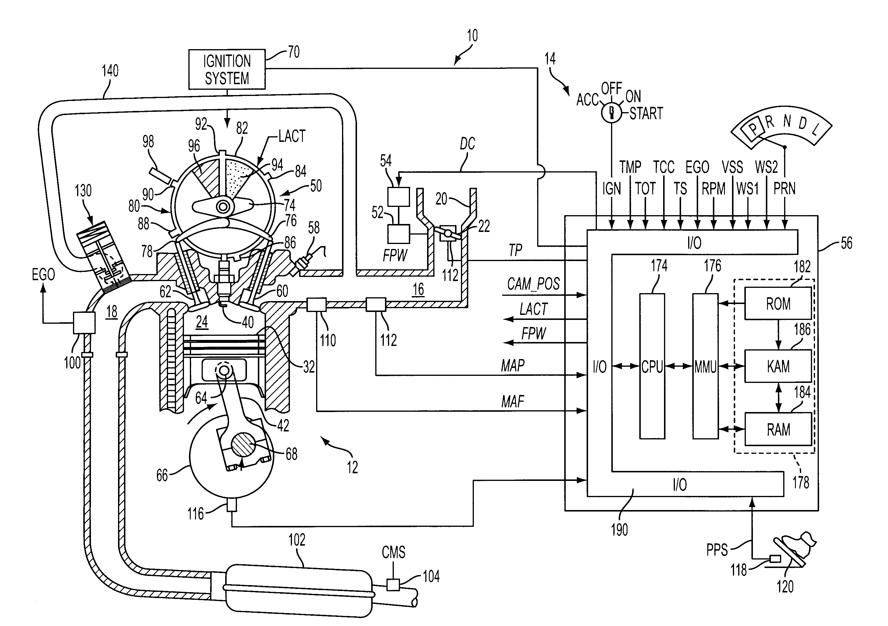
[0014]As those of ordinary skill in the art will understand, various features of the embodiments illustrated and described with reference to any one of the Figures may be combined with features illustrated in one or more other Figures to produce alternative embodiments that are not explicitly illustrated or described. The combinations of features illustrated provide representative embodiments for typical applications. However, various combinations and modifications of the features consistent with the teachings of the present disclosure may be desired for particular applications or implementations. The representative embodiments used in the illustrations relate generally to a spark-ignition multiple-cylinder internal combustion engine having a variable cam timing system that allows control of internal EGR by changing valve timing of intake and exhaust valves. Those of ordinary skill in the art may recognize similar applications or implementations consistent with the present disclosu...


PUM


Abstract

A system and method for controlling a multiple cylinder internal combustion engine include a mechanically operated exhaust gas recirculation valve having a spring-biased pintle with a surface area sized to generate a spring-opposing force to open a valve chamber entrance when an exhaust pressure differential exceeds a first threshold to allow exhaust gas to flow toward an intake and to close a valve chamber exit spaced from the chamber entrance to block exhaust gas flowing to the intake when the pressure differential exceeds a second threshold. The valve operates to limit or block external EGR flow at low load such as during starting and idle as well as at wide-open throttle while metering EGR flow for mid-to-high loads.

Description

BACKGROUND[0001]1. Technical Field[0002]The present disclosure relates to a system and method for controlling exhaust gas recirculation (EGR) for an internal combustion engine using a pintle-type EGR valve.[0003]2. Background Art[0004]Exhaust gas recirculation (EGR) is a well-known engine control strategy that uses a controllable amount of exhaust gas during a subsequent combustion cycle to improve fuel economy and manage emissions. EGR may include internal EGR, or exhaust gas that remains in the cylinders after combustion, and external EGR, which is routed through a pipe or tube from the exhaust back to the intake. The amount of internal EGR can be varied by controlling the open / close timing of the intake and / or exhaust valves. Depending on the particular implementation of the intake and / or exhaust valve control, desired EGR flow may be difficult to obtain under some operating conditions, such as mid-to-high speeds and loads. External EGR is usually controlled by a flow control val...

Claims


Application Information

Patent Timeline
Patent Type & Authority Applications(United States)
IPC IPC(8): F02M25/07
CPCF02M25/0719Y02T10/121F02M25/0777F02M26/16F02M26/57
Inventor GATES, FREEMAN CARTERFARAHMAND, SASSAN
Owner FORD GLOBAL TECH LLC
Why Eureka
Eureka Blog
Learn More