
Polarization conversion element, polarized light illumination optical element, and liquid crystal projector

a technology of polarization conversion and optical element, which is applied in the direction of polarising elements, static indicating devices, instruments, etc., can solve the problems of increasing fabrication costs, increasing the cost of crystal itself, and degrading the polarization conversion efficiency, etc., and achieves suppressing the fabrication cost and satisfying the heat resistance

Inactive Publication Date: 2009-12-03
FUJIFILM CORP
View PDF3 Cites 3 Cited by
  • Summary
  • Abstract
  • Description
  • Claims
  • Application Information

AI Technical Summary

Benefits of technology

The present invention provides a polarization conversion element that can rotate the polarization direction of linear polarized light by 90 degrees, which can be used in a polarized light illumination optical element. The element has good heat resistance and is cost-effective. The invention also provides a polarized light illumination optical element that uses the polarization conversion element and a polarized light beam splitter. The technical effects of the invention include improved optical performance and reduced cost.

Problems solved by technology

Nevertheless, since an organic sheet film is employed for the ½-wavelength plate, fading and a degradation in the polarization conversion efficiency are often arise when the optical element is used near a light source for a long time.
Nevertheless, the crystal itself is expensive.
These situations cause an increase in the fabrication cost.

Method used


Image

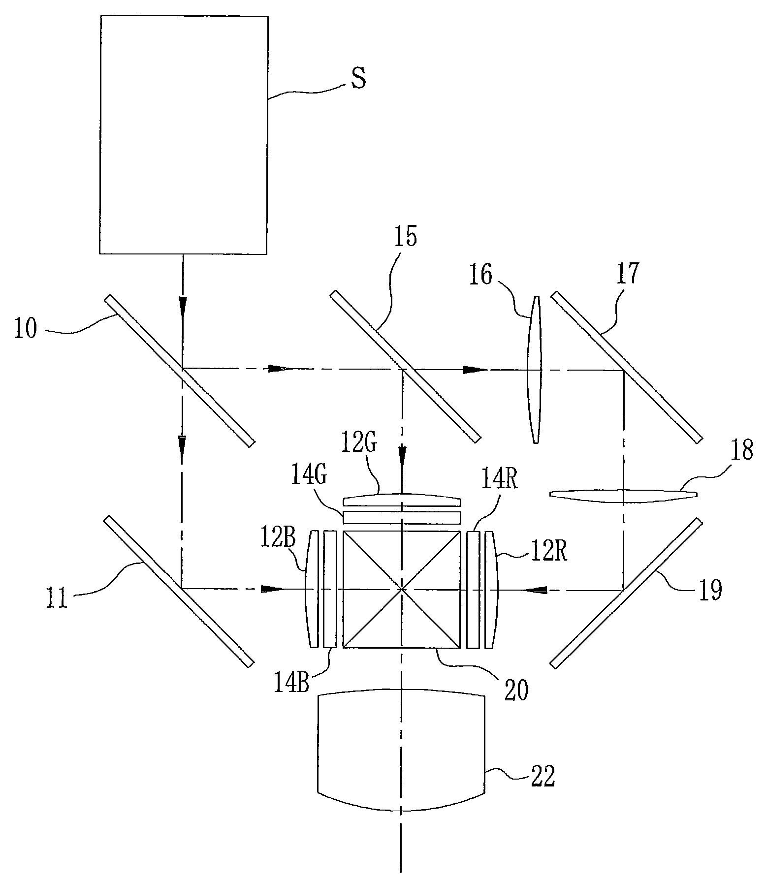
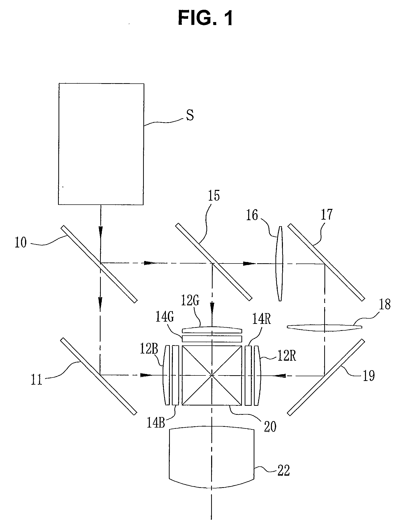
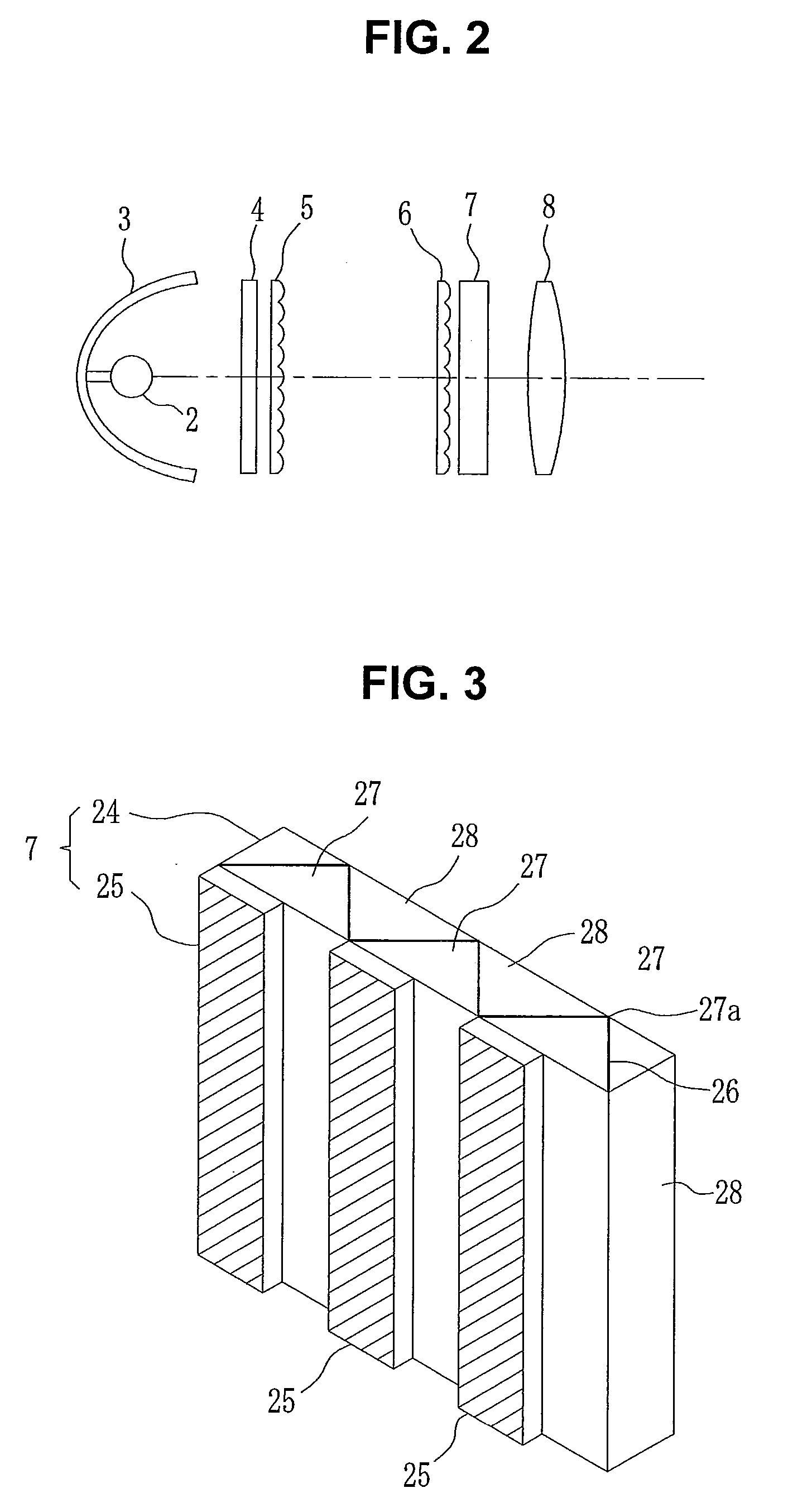
  • Polarization conversion element, polarized light illumination optical element, and liquid crystal projector
  • Polarization conversion element, polarized light illumination optical element, and liquid crystal projector
  • Polarization conversion element, polarized light illumination optical element, and liquid crystal projector

Examples


Embodiment Construction

[0022]According to an exemplary embodiment of the present invention, a polarization conversion element is obtained that has satisfactory heat resistance and a suppressed fabrication cost. Then, when first one of first and second linear polarized light components whose polarization directions are perpendicular to each other enters in the polarization conversion element, this linear polarized light component can efficiently be converted into a second linear polarized light component. Further, when this polarization conversion element is combined with a beam splitter array, for example, non-polarized light emitted from a light source can efficiently be converted into linear polarized light in a state almost completely without light leakage in comparison with the prior art apparatus. Thus, a polarized light illumination optical element suitable for a liquid crystal projector or the like is obtained.

[0023]Hereinafter, exemplary embodiments of the invention will be described in detail by ...


PUM

PropertyMeasurementUnit
incident angleaaaaaaaaaa
angleaaaaaaaaaa
incident angleaaaaaaaaaa

Abstract

A prism sheet is bonded to the bottom faces of rectangular prisms constituting a polarization beam splitter array. In the front face of the prism sheet, a plurality of rectangular prism elements are arranged in parallel to each other and a phase difference compensation film is formed on the surface. The edge lines of the rectangular prism elements are inclined at 45 degrees relative to the edge lines of the rectangular prisms. Linear polarized light of S-polarization component reflected by a polarized light separation film is reflected twice sequentially in a phase difference compensation film formed in a pair of oblique faces of the rectangular prism elements, so that the polarization direction is rotated by 90 degrees and then the light reenters the rectangular prism. Then, the light is transmitted through the polarized light separation film and then extracted from the rectangular prism.

Description

[0001]This application is based on and claims priority under 35 U.S.C §119 from Japanese Patent Application Nos. 2008-145686 and 2008-325732, filed on Jun. 3 and Dec. 22, 2008, respectively, the entire disclosure of which is herein incorporated by reference.BACKGROUND OF THE INVENTION[0002]1. Field of the Invention[0003]The present invention relates to: a polarization conversion element for rotating by 90 degrees the polarization direction of linear polarized light having a fixed polarization direction; a polarized light illumination optical element for converting non-polarized illumination light into linear polarized light having a fixed polarization direction; and a liquid crystal projector whose illumination optical system employs these elements.[0004]2. Description of Related Art[0005]Various kinds of liquid crystal projectors are commercially available in which an image displayed on a liquid crystal display panel is illuminated by light from a light source lamp and then project...

Claims


Application Information

Patent Timeline
Patent Type & Authority Applications(United States)
IPC IPC(8): G02F1/13357G02B5/30
CPCG02B27/286G02F1/13362H04N9/3197G03B21/14H04N9/3167G02F2001/13355G03B21/2073G02F1/13355
Inventor KAWAMURA, YOSHIJI
Owner FUJIFILM CORP
Learn More