
Adaptive Array Antenna Apparatus and Adaptive Control Method Therefor

Inactive Publication Date: 2009-12-03
KYOCERA CORP
View PDF0 Cites 1 Cited by
  • Summary
  • Abstract
  • Description
  • Claims
  • Application Information

AI Technical Summary

Benefits of technology

[0008]In light of the above circumstances, an object of the present invention is to provide an adaptive array antenna apparatus and an adaptive control method therefor, by which the best synchronization timing for adaptive control can be obtained, and the amount of computation can be reduced.
[0026]In accordance with the present invention, a timing which provides a small error to adaptive control can be obtained, and it is possible to release computation resources of an adaptive control process having a large error. Therefore, the best synchronization timing for adaptive control can be obtained, and the amount of the relevant computation can be reduced.

Problems solved by technology

However, in the sliding correlation technique, each antenna generally has an individual correlation-peak timing, and thus it is difficult to obtain the best synchronization timing in the adaptive control.
However, in the conventional technique disclosed in Patent Document 1, as the adaptive control process is executed at each synchronization timing, the amount of computation is large, which may increase the relevant cost.

Method used


Image

  • Adaptive Array Antenna Apparatus and Adaptive Control Method Therefor
  • Adaptive Array Antenna Apparatus and Adaptive Control Method Therefor
  • Adaptive Array Antenna Apparatus and Adaptive Control Method Therefor

Examples


Embodiment Construction

[0037]Below, an embodiment in accordance with the present invention will be explained with reference to the drawings.

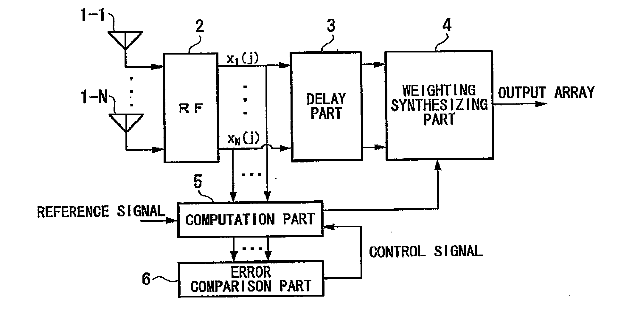
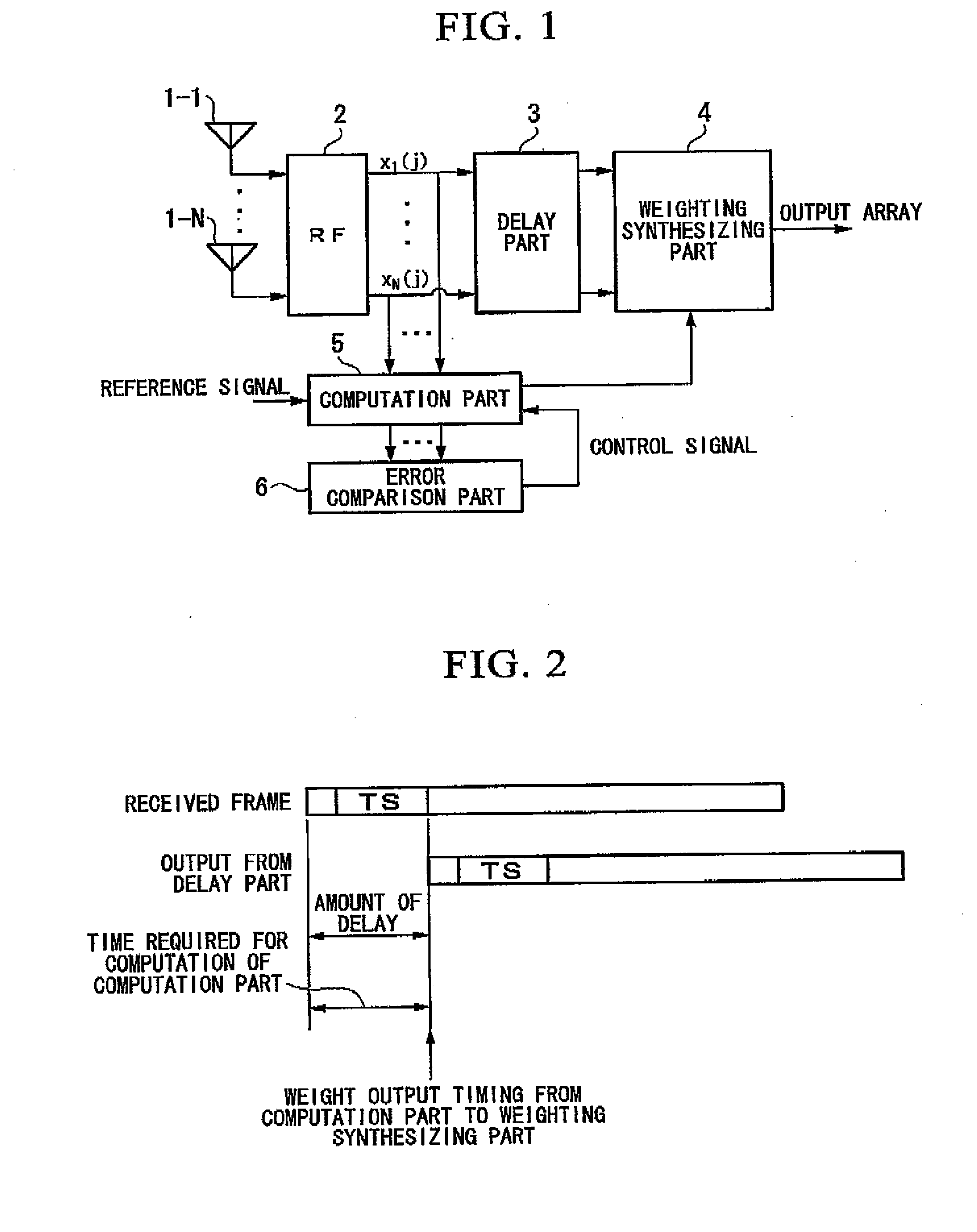
[0038]FIG. 1 is a block diagram showing an adaptive array antenna apparatus as an embodiment of the present invention. The adaptive array antenna apparatus of FIG. 1 includes a plurality of antenna elements 1-1 to 1-N (i.e., N antenna elements) which form an array antenna, a wireless part 2 (RF), a delay part 3, a weighting synthesizing part 4, a computation part 5, and an error comparison part 6.

[0039]In FIG. 1, the wireless part 2 subjects signals, which are received by the antenna elements 1-1 to 1-N, to a wireless reception process (baseband transformation, digitalization, and the like), and outputs received signals x1(j) to xN(j), where j indicates the sampling time. For convenience of explanations, x1(1) to xN(1) indicate the head samples (i.e., first received samples) of each antenna after the wireless reception process, and x1(j) to xN(j) indicate j-th receive...


PUM


Abstract

An adaptive array antenna apparatus for performing adaptive control based on received signals received by a plurality of antenna elements which form an array antenna. The apparatus includes a computation part for computing an error of the received signals at different timings; an error comparison part for comparing the errors at the different timings with each other; and a weighting synthesizing part for performing weighting synthesis based on results of the comparison. Based on the results of the comparison, the computation part releases at least a part of computation resources required for the computation of the errors, and terminates the computation of the errors. Typically, the computation part performs the release of the computation resources when it is determined that the error has a minimum value, and terminates the computation of the errors.

Description

TECHNICAL FIELD[0001]The present invention relates to an adaptive array antenna apparatus and an adaptive control method therefor.[0002]Priority is claimed on Japanese Patent Application No. 2006-050004, filed Feb. 27, 2006, the content of which is incorporated herein by reference.BACKGROUND ART[0003]Conventionally, an adaptive array antenna apparatus has an array antenna including a plurality of antenna elements. Based on a signal received by each antenna element, an adaptive control process is performed so as to control each antenna element.[0004]If an adaptive algorithm based on MMSE (minimum mean square error) is used in such an adaptive control process, a weight array (i.e., arrayed weights) is computed so that the square error between a known part (called a “training sequence”, below) in each received signal and a specific reference signal is minimized. In order to accurately compute the weight array, it is important that the timing of the teaming sequence in each received sig...

Claims


Application Information

Patent Timeline
IPC IPC(8): H04B7/08
CPCH04B7/0894H04B7/0854
Inventor TONG, FANGWEIOKINO, KENTA
Owner KYOCERA CORP
Learn More