Eureka AIR delivers breakthrough ideas for toughest innovation challenges, trusted by R&D personnel around the world.

Suction Filter for Automatic Transmission Fluid

a technology for automatic transmission fluid and suction filter, which is applied in the direction of lubricant mounting/connection, multi-stage water/sewage treatment, separation process, etc., can solve the problem of more expensive manufacture of pleated filters, and achieve high filtration efficiency, high media packaging density, and high dirt holding capacity

Active Publication Date: 2009-12-03
FORD GLOBAL TECH LLC
View PDF16 Cites 35 Cited by
  • Summary
  • Abstract
  • Description
  • Claims
  • Application Information

AI Technical Summary

Benefits of technology

[0010]The suction filter that provides high media packaging density, high dirt holding capacity, high filtration efficiency, packaging flexibility for irregular shaped housings, and low cost

Problems solved by technology

This design has an inherit weaknesses: its overall capacity balanced against its efficiency and pressure drop.
The tradeoff, however, is two fold: a pleated filter is more expensive to manufacture, but pleated technology allows only a rectangular housing configuration.

Method used


Image

  • Suction Filter for Automatic Transmission Fluid
  • Suction Filter for Automatic Transmission Fluid
  • Suction Filter for Automatic Transmission Fluid

Examples


Embodiment Construction

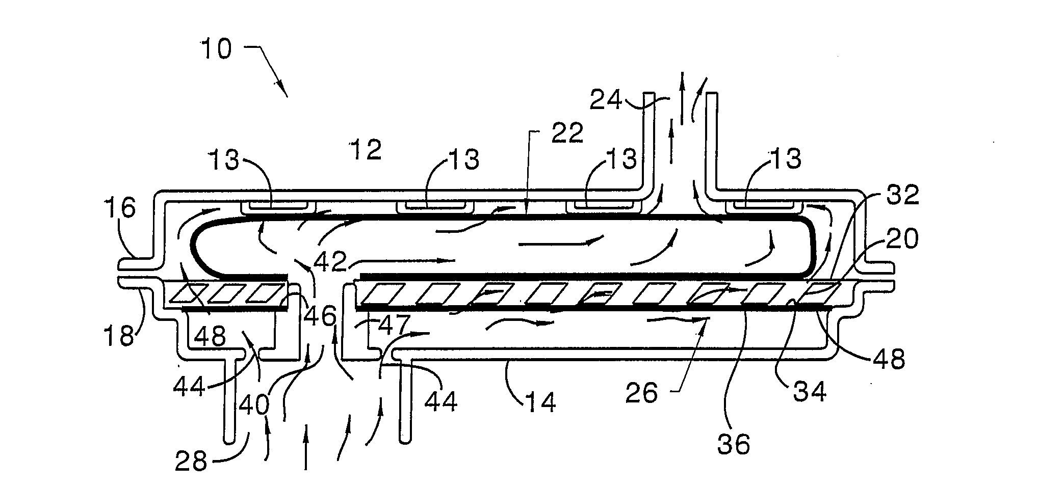
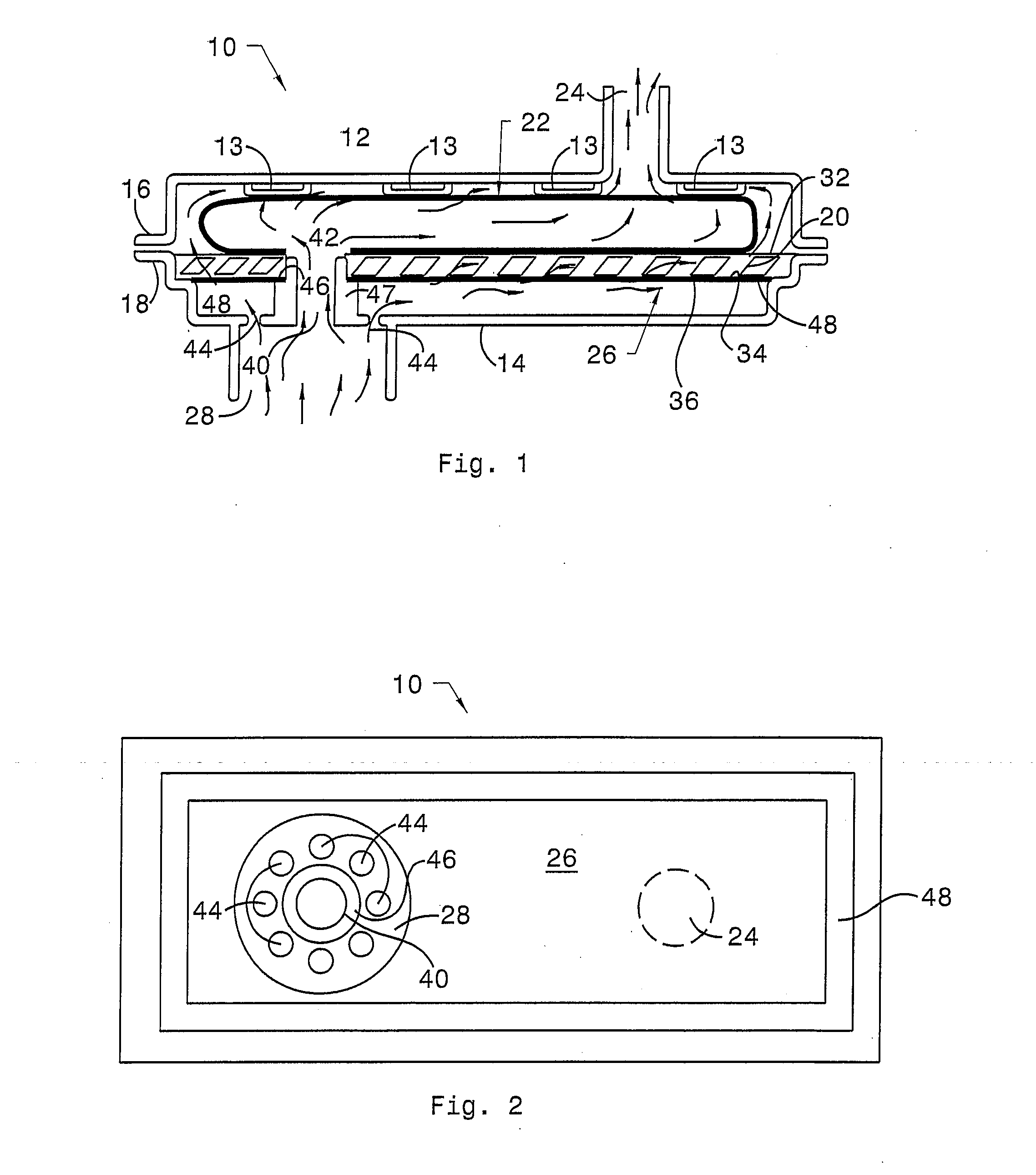
[0022]Referring now to the drawings, there is illustrated in FIG. 1 a suction filter 10 that includes an upper housing 12 provided with internal supporting ribs 13, a lower housing 14 secured to the upper housing at peripheral flanges 16, 18, a separator grid 20 located in the lower housing between, a coarse media bag 22 located in the upper housing between an outlet 24 and the separator grid, and a fine media 26 located in the lower housing between a passageway 28 and the separator grid.

[0023]Preferably, the separator grid 20 is a molded component comprising canted ribs 38 connected by narrow horizontal ribs 32, 36, which support the two filtering layers and provide flow channels for fluid that passes through the high efficiency, fine media layer 26. A lower surface 30 of the coarse media bag 22 contacts a surface of the upper rib 32 of the separator grid 2, and an upper surface of the coarse media contacts the lower surface of internal supporting ribs 13. An upper surface 34 of th...


PUM

PropertyMeasurementUnit
Flow rateaaaaaaaaaa

Abstract

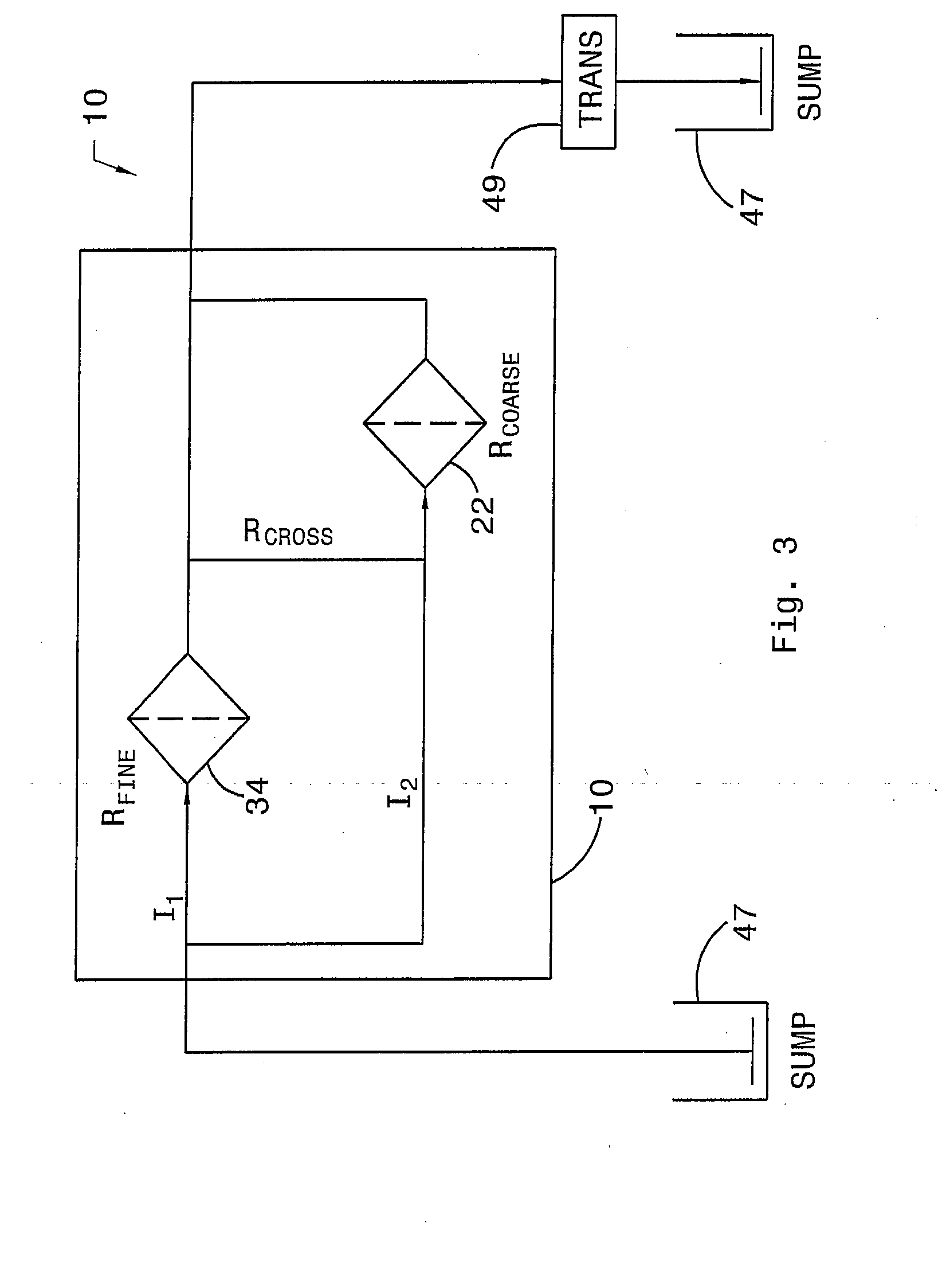
An assembly for filtering contaminants from automatic transmission fluid includes a housing including a first inlet and a second inlet, through which fluid enters the housing, and an outlet, through which fluid exits the housing; a first media filter located within the housing in a first fluid flow path between the first inlet and the outlet; and a second media filter located within the housing in a second fluid flow path between the second inlet and the outlet.

Description

BACKGROUND OF THE INVENTION[0001]1. Field of the Invention[0002]This invention relates generally to a suction filter with multiple filtration elements that are fed from multiple inlets for an automatic transmission.[0003]2. Description of the Prior Art[0004]A simple transmission suction filter has a single media layer that is crimped on the edges between the housing flanges. This design has an inherit weaknesses: its overall capacity balanced against its efficiency and pressure drop. As more efficient media have higher flow resistance, i.e., lower permeability, a single media layer filter must be quite larger to handle the required transmission flow without having an excessive pressure drop at cold temperatures when the viscosity of the transmission fluid is highest.[0005]Most transmission suction filters use a bag filter media arrangement, which provide higher media packaging density. This allows an increased area for fluid flow, which results in a lower pressure drop and higher di...

Claims


Application Information

Patent Timeline
IPC IPC(8): B01D29/05
CPCB01D29/05B01D35/0273B01D29/27B01D29/56
Inventor PEKARSKY, LEVPRATT, ROBB D.
Owner FORD GLOBAL TECH LLC
Why Eureka
Eureka Blog
Learn More