
Method for controlling an automated friction clutch

a technology of friction clutches and friction plates, applied in the direction of clutches, instruments, computing, etc., can solve the problems of limited adaptation methods of automated friction clutches, and achieve the effect of increasing the accuracy of clutch control

Inactive Publication Date: 2009-11-12
ZF FRIEDRICHSHAFEN AG
View PDF10 Cites 8 Cited by
  • Summary
  • Abstract
  • Description
  • Claims
  • Application Information

AI Technical Summary

Benefits of technology

[0016]The constant control or actuation of the clutch control element is produced, if it is designed as a pressure-medium-actuated control cylinder, by a constant throttle cross-section of an associated proportional valve or by a constant frequency of an associated frequency-modulated pulse valve, and if it is of electro-mechanical design, by a constant current or voltage gradient of the associated electric motor. The method according to the invention only presupposes the presence of a regulation path sensor and a timer which, however, are in any case present in an automated clutch control. Consequently no additional sensor is needed for the implementation of the method. Accordingly, the method can be integrated into any control device of an automated diaphragm spring clutch without much effort or cost.
[0021]To largely exclude the influence of rate-dependent forces on the determination of the end point xLE, it is advantageous to carry out the disengagement of the friction clutch with constant control or actuation of the clutch control element which, in the linear increase range at the beginning of the release travel path xK(t), corresponds to a minimum disengagement rate vK<sub2>—< / sub2>min lower than a nominal disengagement rate vK<sub2>—< / sub2>soil used in normal operation (vK≈vK<sub2>—< / sub2>min or vK<vK<sub2>—< / sub2>soil).
[0024]To increase the accuracy of the clutch control it can also be expedient to carry out the correction of a control parameter of the clutch control element in accordance with the invention also during the driving operation of the motor vehicle at regular time intervals, in each case during a driving pause in connection with a driving-operation-independent actuation of the clutch and / or, during driving, in connection with a starting- or gearshift-related actuation of the clutch.

Problems solved by technology

Known adaptation methods for automated friction clutches have hitherto been limited to the determination of inflection points on the respective torque characteristic representing the torque that can be transmitted by the friction clutch as a function of the regulating path.
The disadvantage of this procedure, however, is that besides a path sensor an additional force sensor is needed, and the discontinuity in question in the gradient variation of the releasing force FKA(xK) only occurs in significant form when the driving disk has a rigid lining with no spring.

Method used


Image

  • Method for controlling an automated friction clutch
  • Method for controlling an automated friction clutch
  • Method for controlling an automated friction clutch

Examples


Embodiment Construction

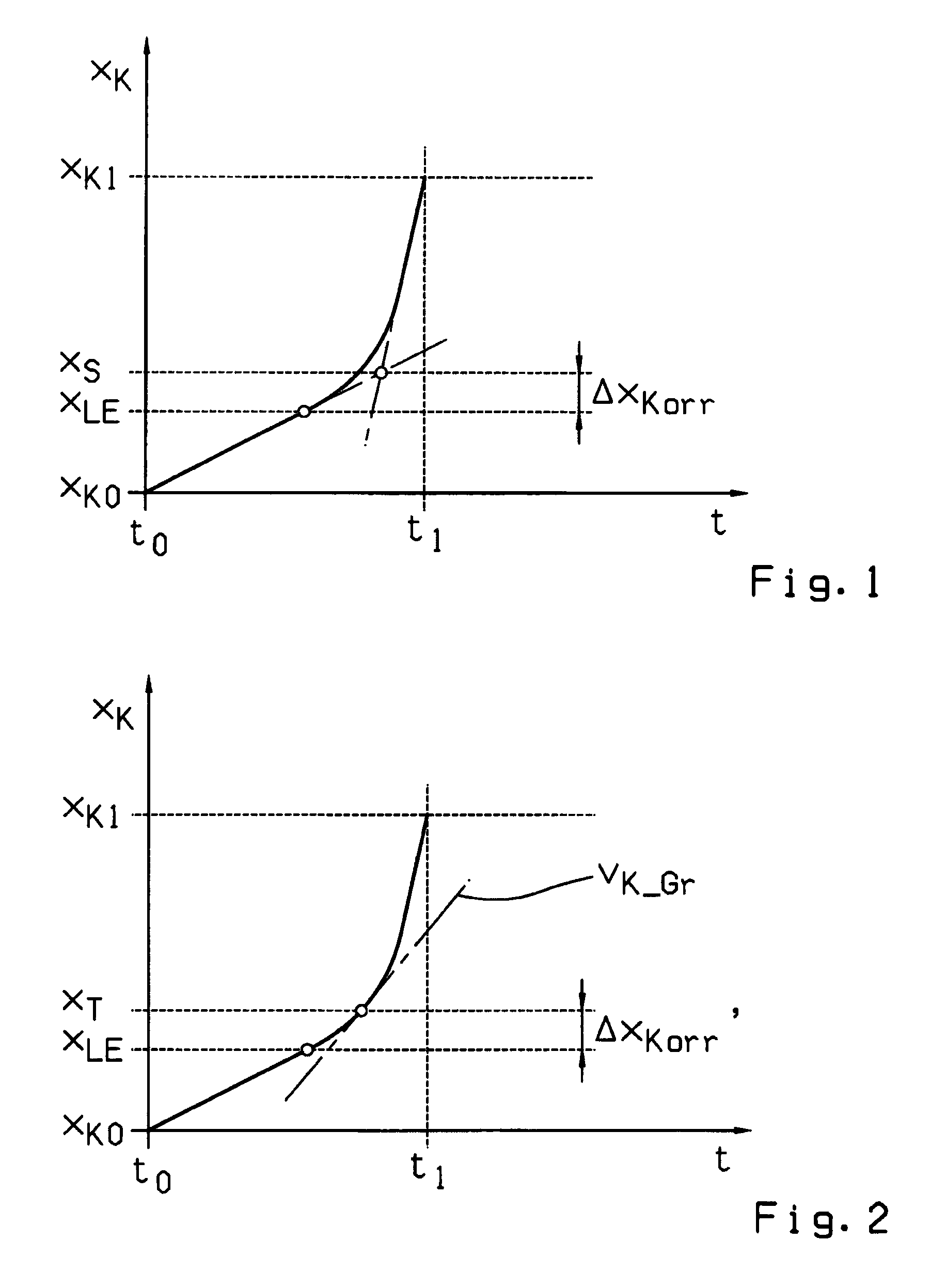
[0031]The continuous line in the diagram of FIG. 1 represents the time variation of the release travel path xK(t) for a diaphragm spring clutch during its actuation, produced during a continuous control or actuation of the clutch control element, i.e. during constant increase of the releasing force. Thus, the time variation of the release travel path xK(t) from the beginning of the disengagement process at time t0 until the end of the disengagement process at time t1 consists of a small linear increase of the release travel path xK(t) at the beginning of the disengagement process, followed by a progressive rise of the release travel path xK(t), i.e. a clear increase of the disengagement rate vK=dxK / dt, and then a substantially linear and steeper increase of the release travel path xK(t) toward the end of the disengagement process.

[0032]The linear rise of the release travel path xK(t) of small inclination at the beginning of the disengagement process corresponds to the linear increas...


PUM


Abstract

A method of controlling an automated friction clutch in a drivetrain of a motor vehicle between a drive motor and a manual transmission. During clutch actuation, at least one operating parameter of the friction clutch is detected by a sensor and from variation of the operating parameter at least one adaptation parameter is derived for correcting a control parameter of the associated clutch control element. To obtain information about variation of the clutch release force and to improve the control of an associated clutch control element, the friction clutch is fully disengaged with constant control or actuation of the clutch control element. During the disengagement process, the release travel path is determined as a function of release time, and from the time variation of the release travel path, a characteristic value is determined which is used to determine an adaptation parameter for correcting the control parameter of the clutch control element.

Description

[0001]This application claims priority from German patent application serial no. 10 2008 001 628.9 filed May 9, 2008.FIELD OF THE INVENTION[0002]The invention concerns a method for controlling an automated friction clutch which is made as a diaphragm spring clutch and is arranged as a starting and shifting clutch in a drivetrain of a motor vehicle between a drive motor and a manual transmission, in such manner that during clutch actuation at least one operating parameter of the friction clutch is detected by sensor means, and from the variation of this operating parameter at least one adaptation parameter is derived for the correction of a control parameter of the associated clutch control element.BACKGROUND OF THE INVENTION[0003]Diaphragm spring clutches have been known for a long time and, owing to their robust and space-saving structure, have become well established particularly in motor vehicles as the preferred design for passively engaging, dry-operating clutches. In a diaphra...

Claims


Application Information

Patent Timeline
IPC IPC(8): G06F17/00
CPCF16D48/06F16D2500/3023F16D2500/3026F16D2500/70605F16D2500/50251F16D2500/70412F16D2500/50248
Inventor PETZOLD, RAINERHERTER, PETERBITZER, FRANZMAIR, ROLAND
Owner ZF FRIEDRICHSHAFEN AG
Learn More