Bioabsorbable Polymeric Composition for a Medical Device
a technology of bioabsorption and medical devices, applied in the field of new polymer compositions, can solve problems such as scar tissue coating formation, and achieve the effect of less inflammation and lower potential for trauma
- Summary
- Abstract
- Description
- Claims
- Application Information
AI Technical Summary
Benefits of technology
Problems solved by technology
Method used
Image
Examples
example 1
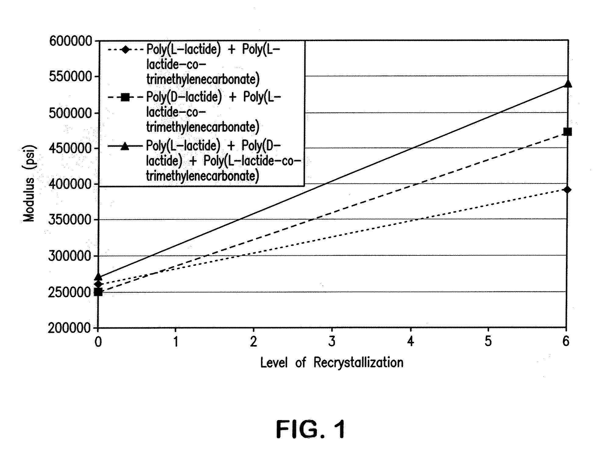
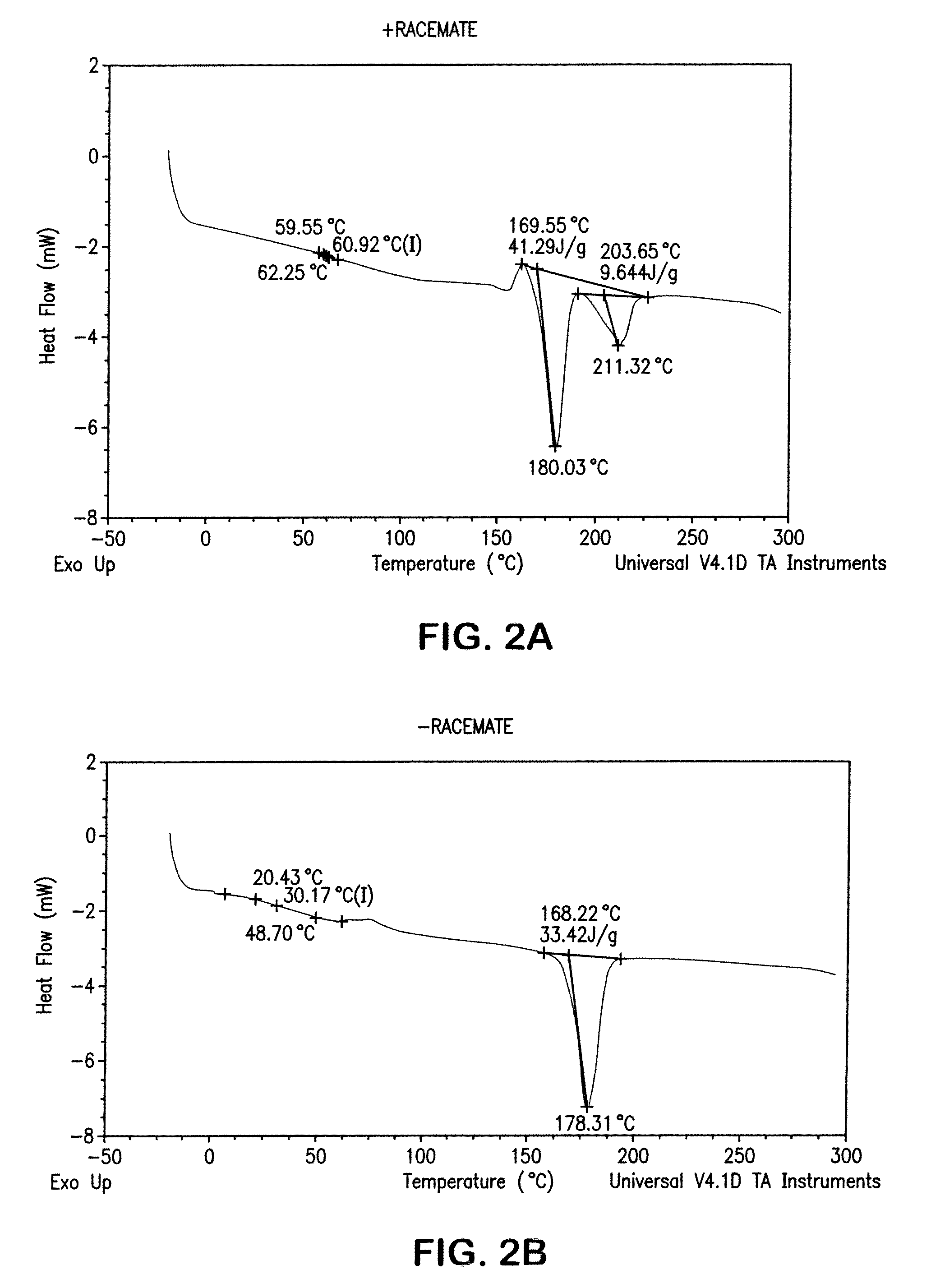
[0069]A test disk was injection molded from a composition of a racemic mixture of poly(L-lactide) and poly(D-lactide) with 15% by weight copolymer modifier of a 50:50 molar ratio poly(L-lactide-co-TMC). Injection cylinder temperatures were between 110° C. and 225° C. with a mold temperature of 50° F. to 82° F., to mold an amorphous disk. Injection pressure was set between 1300 and 1450 psi with a 50 second cycle time. It was found that an adequate degree of crystallinity could be produced in the polymer. DSC analysis confirmed the formation of both the conventional lactide crystal and the racemate crystal morphology.
example 2
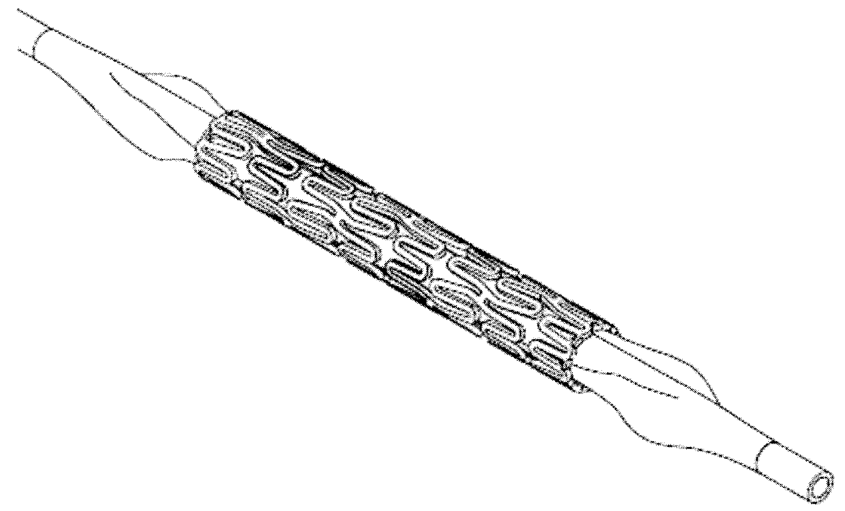
[0070]The polymer mixture is blend extruded into a narrow tube, and a scaffold form may be cut with a laser under a microscope to produce a cage-like mesh device of meandering struts connected to hoop-like rings positioned at one end and / or at the middle portion of the device. The resulting scaffold device includes a primary meandering scaffold forming a circumferential mesh structure containing a pattern of secondary meandering struts nested within the scaffold as well as at or near the ends of the scaffold. The second meandering struts may be shaped to form upon full implant expansion, a less sinusoidal or more straight hoop or ring shape than the first meandering struts, in orthogonal direction to the longitudinal axis of the tubal device. The expanded second meandering struts having smaller or shorter meandering loops or curves are stretched further during expansion. These struts may form thus hoops of greater crystallinity and therefore greater rigidity with elasticity so that ...
example 3
[0071]The polymer compositions may be prepared from commercially available granular materials and copolymer additives. The dry components are weighed according to the desired weight ratio into a container rotating in a suitable for 30 minutes or until a homogenous mixture is obtained followed by further drying in vacuo at 60° C. for 8-12 hours or overnight. As described above, the thoroughly mixed components may be melt blended and injection molded into a pair of matching plates. The composition rendering polymer sheets exhibiting a suitable elasticity and an appearance of amorphous morphology or very low degree of crystallinity under a polarizing light source may be extruded with a back pressure of 40-50 bar under melting temperature of 120-160° C. while being homogenized with a 28 blade screw at 40-80 rpm. The extruder melt blending and homogenization conditions of the material during metering phase of the process may include a screw speed of 60-100 rpm. The relatively mild inject...
PUM
| Property | Measurement | Unit |
|---|---|---|
| temperature | aaaaa | aaaaa |
| mold temperature | aaaaa | aaaaa |
| mold temperature | aaaaa | aaaaa |
Abstract
Description
Claims
Application Information
 - R&D
- Intellectual Property
- Life Sciences
- Materials
- Tech Scout
- Unparalleled Data Quality
- Higher Quality Content
- 60% Fewer Hallucinations
Browse by: Latest US Patents, China's latest patents, Technical Efficacy Thesaurus, Application Domain, Technology Topic, Popular Technical Reports.
© 2025 PatSnap. All rights reserved.Legal|Privacy policy|Modern Slavery Act Transparency Statement|Sitemap|About US| Contact US: help@patsnap.com


