
Mems-based nanopositioners and nanomanipulators

a technology of nanopositioners and manipulators, applied in manipulators, electrical apparatus, electrostatic generators/motors, etc., can solve the problems of difficult temperature control at the probe tip, preventing the use of temperature sensitive applications, and limited application of this device, etc., to achieve fast response, high repeatability, and precise closed-loop control

Inactive Publication Date: 2009-11-12
SUN YU +1
View PDF9 Cites 13 Cited by
  • Summary
  • Abstract
  • Description
  • Claims
  • Application Information

AI Technical Summary

Benefits of technology

[0015]In one aspect of the present invention, a MEMS-based nanomanipulator is provided which can achieve both sub-nanometer resolution and millimeter force output.
[0016]In another aspect of the present invention, an integrated displacement sensor is provided to obtain position feedback that will enable precise closed-loop control during nanomanipulation and nanopositioning.
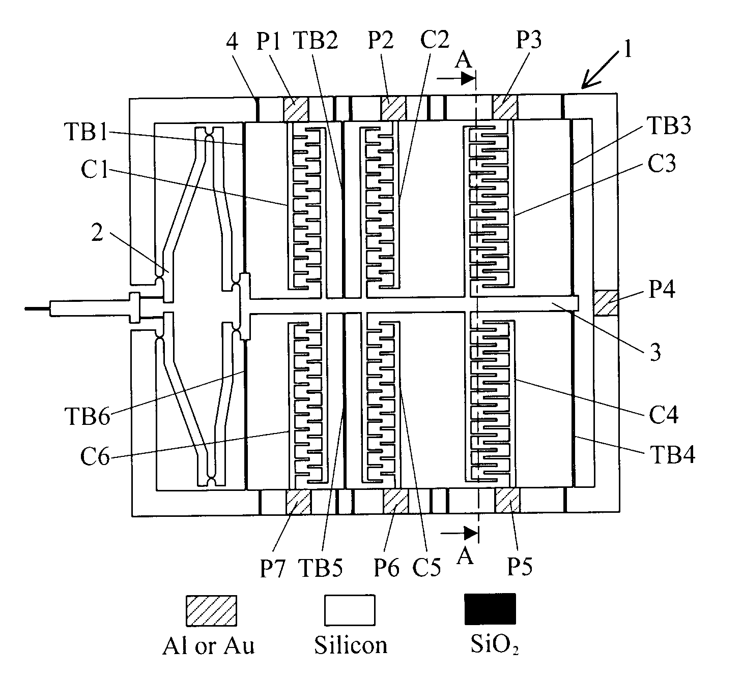
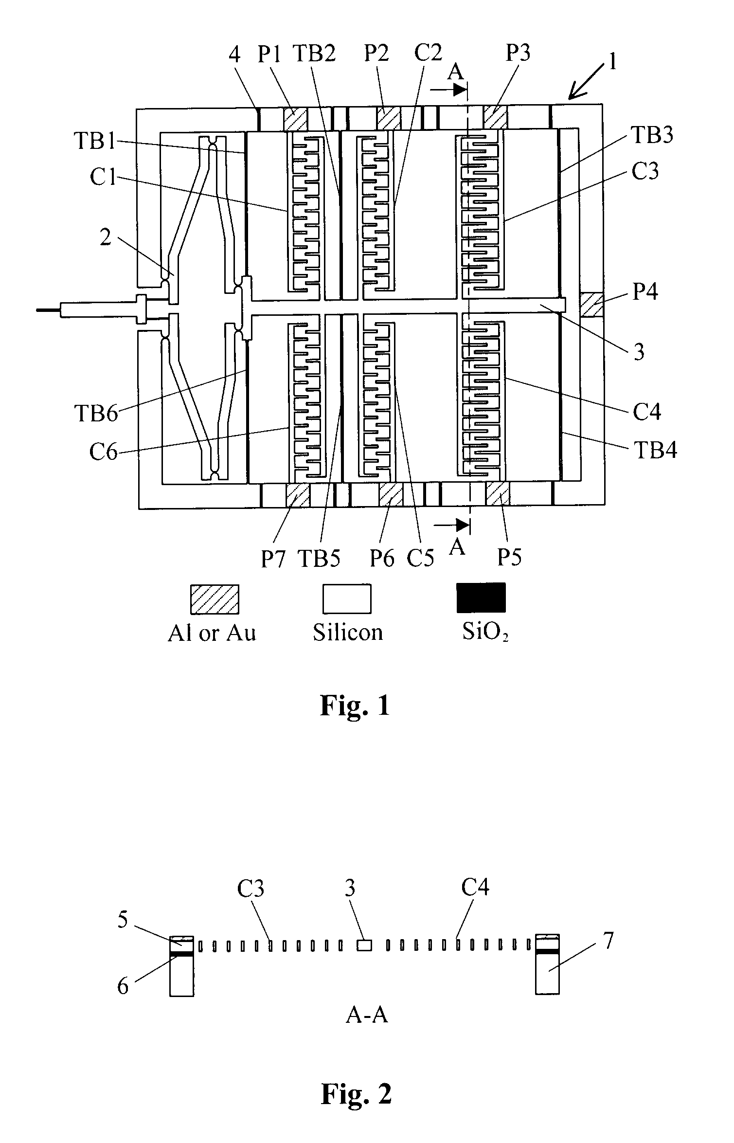
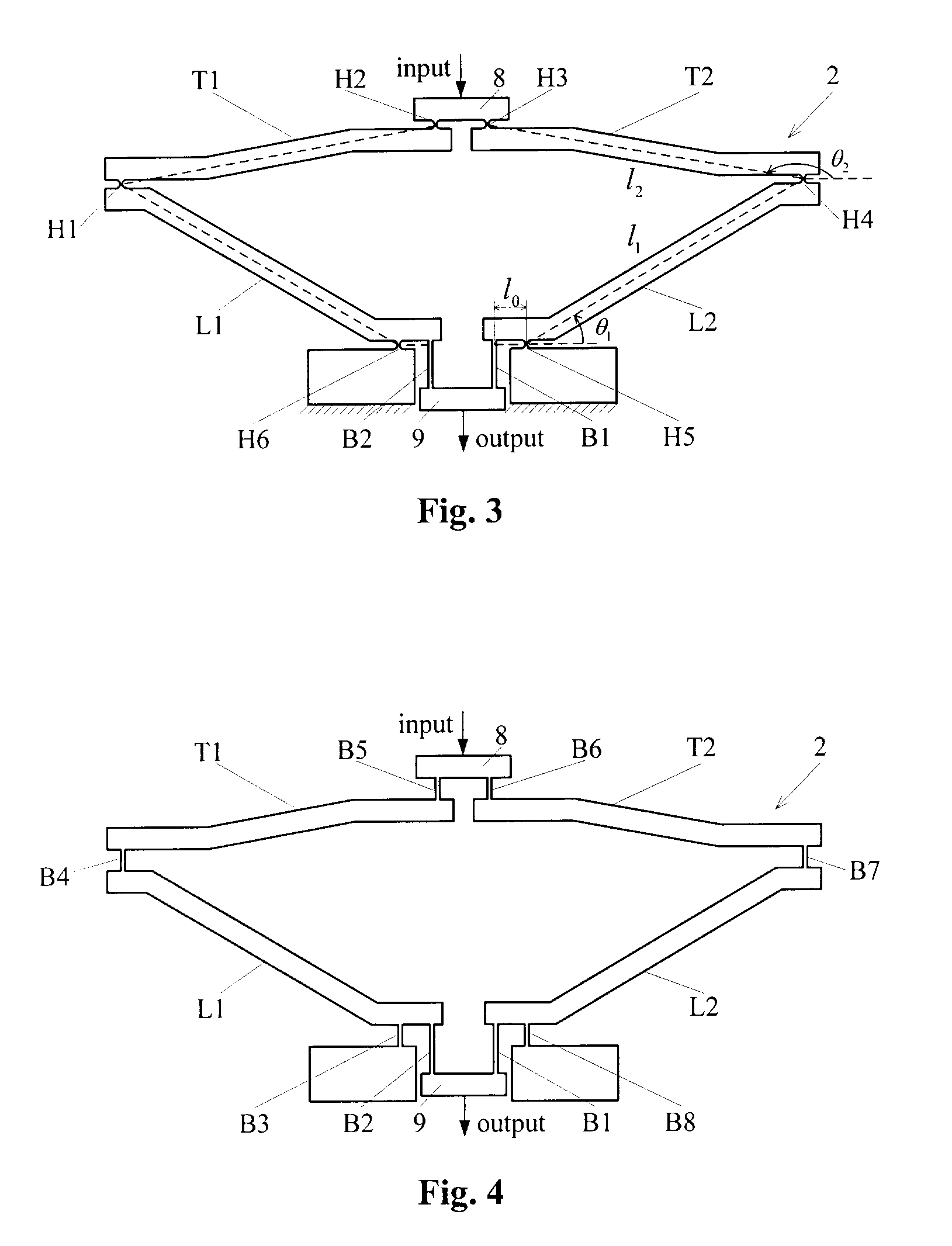
[0017]In an embodiment of the present invention, a nanomanipulator leverages the high repeatability and fast response of MEMS electrostatic microactuators while overcoming the limitation of low output forces. The device integrates a highly linear amplification mechanism, a lateral comb-drive microactuator, and a capacitive position sensor. The amplification mechanism is used to minify input displacements provided by the comb-drive microactuator for achieving a high positioning resolution at the output probe tip and to amplify output forces for manipulating nano-objects. The capacitive position sensor is placed at the input end as a position encoder to measure the input displacement. The strict linearity of the amplification mechanism guarantees that the position sensor can provide precise position feedback of the output probe tip, allowing for closed-loop controlled nanomanipulation.

Problems solved by technology

However, the application of this device is limited by its sub-micronewton force output.
Although electrothermal microactuation provides much larger output forces, hysteresis and thermal drift make the positioning accuracy relative low (tens to hundreds of nanometers) in open-loop operations.
Furthermore, the difficulty of well controlled temperatures at the probe tip prevents its use in temperature sensitive applications.
However, inherent hysteresis and creep of piezoelectric actuators result in significant open-loop positioning errors, and therefore, demand sophisticated compensation control algorithms.
Besides the high cost, the large sizes of commercially available piezoelectric nanomanipulators (5 cm to 20 cm) limit their use when applications have stringent space constraints.
Although this system can be installed inside an SEM, it is too large to fit in the chamber of a TEM.
However, inherent hysteresis and creep of piezoelectric actuators result in significant open-loop positioning errors, and therefore, demand sophisticated compensation control algorithms.
Besides the high cost, the large sizes of commercially available piezoelectric nanomanipulators (5 cm to 10 cm) limit their use when applications have stringent space constraints, particularly inside TEMs.
Although MEMS-based nanomanipulators have such advantages as low cost, small size, fast response, and flexibility for system integration, existing MEMS devices (e.g., electrostatic actuators and electrothermal actuators) are not capable of achieving both high positioning resolution and large force output.

Method used


Image

  • Mems-based nanopositioners and nanomanipulators
  • Mems-based nanopositioners and nanomanipulators
  • Mems-based nanopositioners and nanomanipulators

Examples


Embodiment Construction

[0029]The present invention provides a MEMS-based nanomanipulator which can achieve both sub-nanometer resolution and millimeter force output. An integrated displacement sensor is also provided to obtain position feedback that enables precise closed-loop control during nanomanipulation.

[0030]It should be expressly understood that the present invention functions either as a nanomanipulator or as a nanopositioner. As a nanomanipulator, besides the applications described herein, the device can be applied to precisely interacting with biological molecules, such as for biophysical property characterization or precisely picking and placing nano-sized objects, such as nanotubes / wires and nano particles. As a nanopositioner, the device can find a range of precision applications for in-plane positioning, for example, as an x-y precision positioner that can be mounted on the suspension head of a computer harddrive for data transfer. Currently, a meso-scaled piezoelectric positioner is used on...


PUM


Abstract

A MEMS-based mano manipulator or nanopositioner is provided that can achieve both sub-nanometer resolution and millimeter force output. The nanomanipulator or nanopositioner comprises a linear amplification mechanism that minifies input displacements and amplifies input forces, microactuators that drive the amplification mechanism to generate forward and backward motion, and position sensors that measure the input displacement of the amplification mechanism. The position sensors obtain position feedback enabling precise closed-loop control during nanomanipulation.

Description

PRIORITY[0001]This application claims the benefit of Canadian Patent No. 2,551,194, filed 23 Jun. 2006.FIELD OF THE INVENTION[0002]The present invention relates to nanotechnology and nanoscience and engineering.BACKGROUND OF THE INVENTION[0003]Microelectromechanical Systems (“MEMS”) refers to technology on a very small scale, and converges at the nano-level into nanoelectromechanical systems (“NEMS”) and nanotechnology, although NEMS can also refer to nano devices employing nano-scaled materials as active elements.[0004]Recent advances in nanoscience and nanotechnology, including the manipulation and characterization of nano-materials (e.g., carbon nanotubes, silicon nanowires, and zinc oxide nanorods) and NEMS development, require manipulators with a nanometer positioning resolution, micrometer motion range, high repeatability, and large force output (i.e. payload driving capability). At present, the most common nanomanipulator used for precise positioning and manipulation inside S...

Claims


Application Information

Patent Timeline
IPC IPC(8): H02N1/00
CPCB25J9/0015B25J7/00
Inventor SUN, YULIU, XINYU
Owner SUN YU
Learn More