
Insulated substrate impedance transducers

a technology of impedance transducer and substrate, which is applied in the direction of resistance/reactance/impedence, instruments, biochemical apparatus and processes, etc., can solve the problem of affecting measurement resolution, affecting the efficiency of silver coverage sensor, and not fully characterized effects, etc. problem, to achieve the effect of preserving the efficiency of silver coverage below 30% and reducing the dimensions below

Inactive Publication Date: 2009-11-05
UNIVERSITE CATHOLIQUE DE LOUVAIN +1
View PDF10 Cites 21 Cited by
  • Summary
  • Abstract
  • Description
  • Claims
  • Application Information

AI Technical Summary

Benefits of technology

[0015]It is an object of the present invention to provide an alternative or good apparatus and method for detecting the presence of and / or characterising target materials in solid, liquid or gaseous media by electronic transduction of physico-chemical stimuli through impedance measurements.
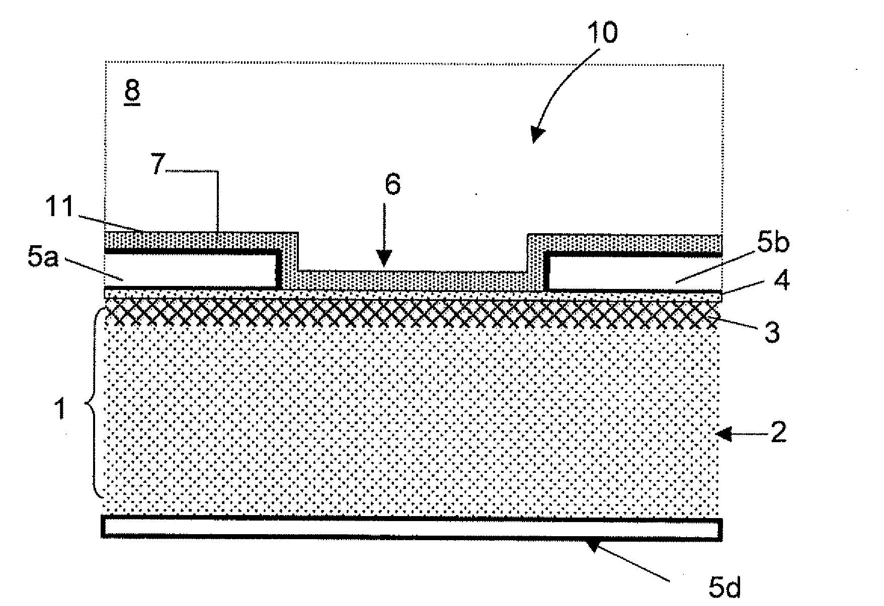
[0026]It is a further advantage of the transducer according to embodiments of the present invention that insulated measurement electrodes are electrically coupled with semiconductor elements, which allows benefiting from dielectric impedance changes induced by field-effect as well as chemical reaction, illumination or mechanical constraint.
[0029]An advantage hereof is that the back-gate electrode allows tuning of the working range of the solid-state electronic.
[0037]The transducer may have a top surface, and the top surface of the transducer may be provided with conductive, e.g. metallic, or semiconductive particles or grains. The surface coverage with such conductive or semiconductive particles or grains may be at least between 0% and 30% but may preferably be as high as possible, e.g. may reach substantially 100%. These conductive, e.g. metallic, or semiconductive particles or grains may have the function of labels and may also be provided for selectively binding specific target materials. The presence of conductive, e.g. metallic, or semiconductive particles or grains on the transducers surface leads to a decrease of capacitance cut-off frequency.
[0046]It is an advantage of embodiments according to the present invention that insulated measurement electrodes are electrically coupled with semiconductor elements, which allows benefiting from smart dielectric impedance changes induced by field-effect as well as chemical reaction, illumination or mechanical constraint.
[0047]It is a further advantage of embodiments according to the present invention that it presents a new design approach, which is associated to a powerful frequency- and time-domain measurement method, which is known in theoretical literature but which is not familiar with integrated sensors.

Problems solved by technology

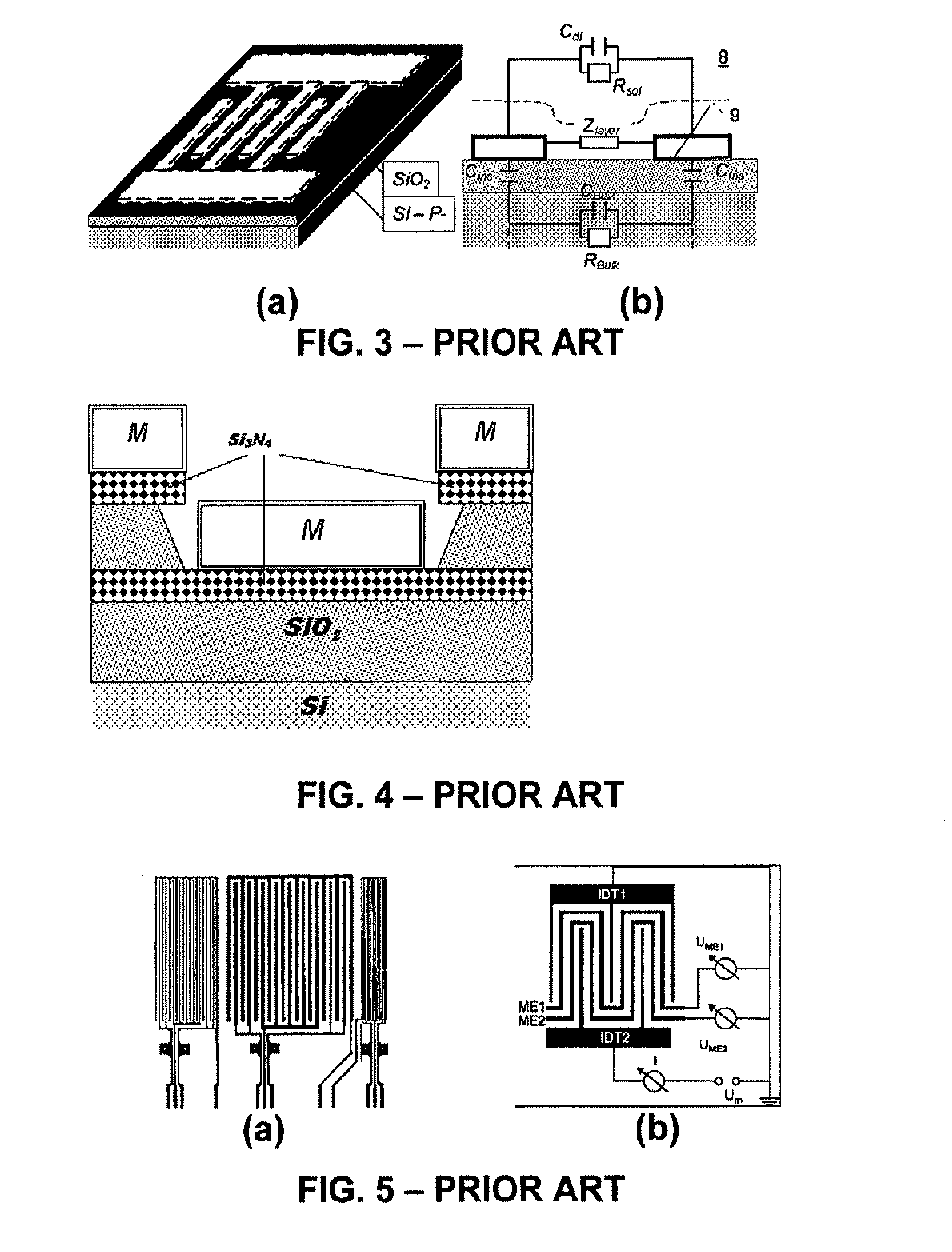
Since the properties of the supports do not respond to extrinsic stimuli, they introduce parasitic elements in the electrical model used for data interpretation, which subsequently affects measurement resolution.
However, the effect is not completely characterized and is attributed to a modification of the chemical reaction itself.
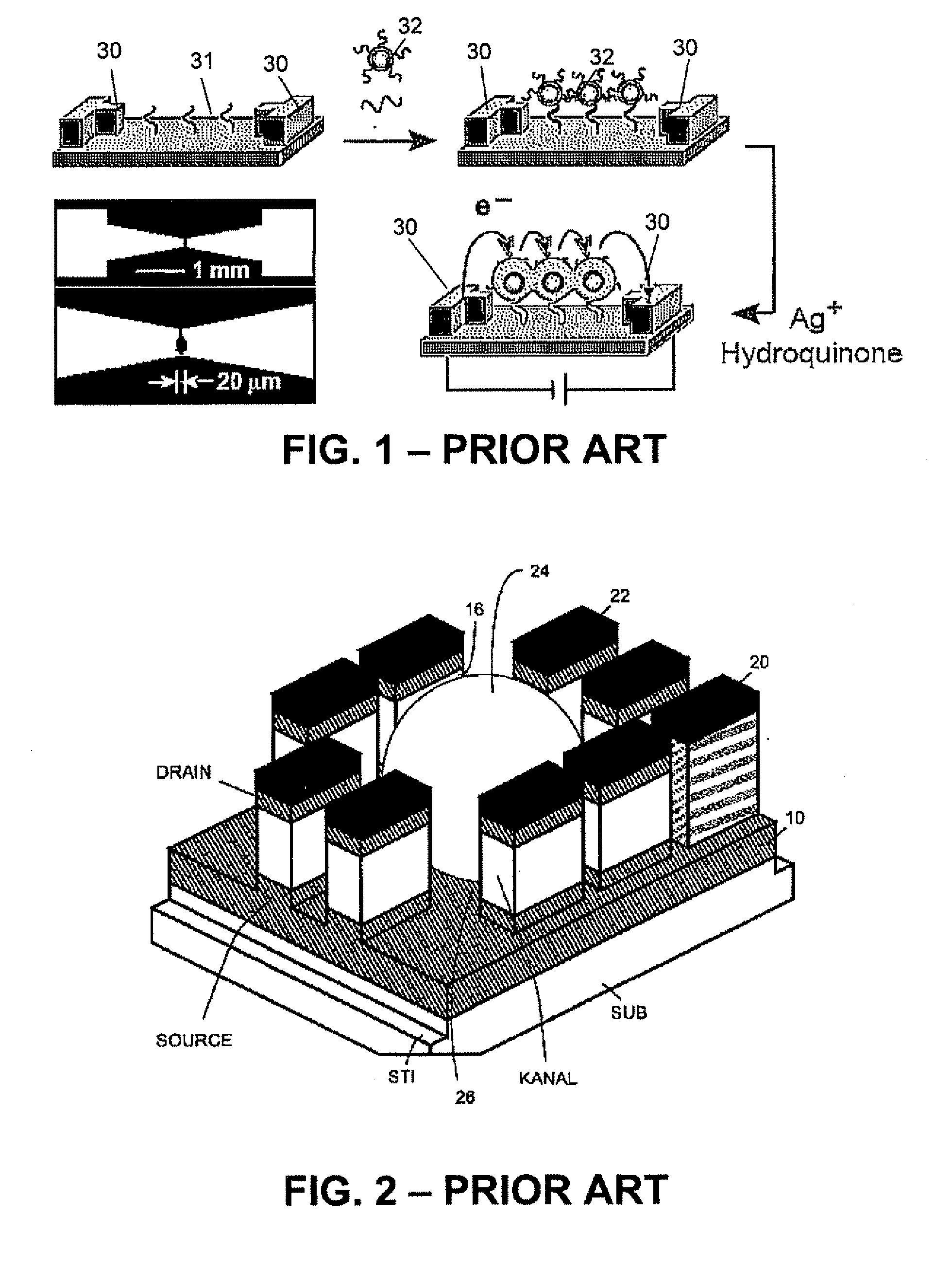
However, the sensor's efficiency for a silver coverage lower than 30% can only be preserved at the cost of reducing their dimensions below 1 μm, especially reducing digit spacing.

Method used


Image

  • Insulated substrate impedance transducers
  • Insulated substrate impedance transducers
  • Insulated substrate impedance transducers

Examples


Embodiment Construction

[0068]The present invention will be described with respect to particular embodiments and with reference to certain drawings but the invention is not limited thereto but only by the claims. The drawings described are only schematic and are non-limiting. In the drawings, the size of some of the elements may be exaggerated and not drawn on scale for illustrative purposes The dimensions and the relative dimensions do not correspond to actual reductions to practice of the invention.

[0069]Furthermore, the terms first, second, third and the like in the description and in the claims, are used for distinguishing between similar elements and not necessarily for describing a sequential or chronological order. It is to be understood that the terms so used are interchangeable under appropriate circumstances and that the embodiments of the invention described herein are capable of operation in other sequences than described or illustrated herein.

[0070]Moreover, the terms top, bottom and the like ...


PUM

PropertyMeasurementUnit
Temperatureaaaaaaaaaa
Dielectric polarization enthalpyaaaaaaaaaa
Pressureaaaaaaaaaa

Abstract

The present invention provides an electronic transducer (10) and a method for detecting and / or characterizing target materials or physico-chemical stimuli in an external medium (8) using the electronic transducer (10). The electronic transducer (10) comprises a sensing element (3) featuring a variable conductance when exposed to a stimulus from the external medium and a first and second electrode (5a, 5b) spaced apart on or in a sensing material surface of a substrate, the sensing element being provided in or on the substrate and being located between the first and the second electrodes (5a, 5b) forming a pair of sensing electrodes for sensing a change in conductance of the sensing element (3) in a direction substantially parallel to the sensing material surface, at least one of the sensing electrodes (5a, 5b) being electrically insulated from the sensing element (3) by a dielectric layer (4), so as to be capacitively coupled to the sensing element (3). An insulating layer or target specific layer (7) may optionally be provided covering the sensing element (3) and optionally the sensing electrodes and being adapted for contact with the external medium (8). Electrical measurements made between the pair of sensing electrodes (5a, 5b) are influenced by the impedance of the channel (3) which is affected by the presence of the medium (8) to be tested.

Description

TECHNICAL FIELD OF THE INVENTION[0001]The present invention relates to electronic transducers, more particularly to insulated substrate impedance transducers or ISITs, and to a method for detecting the presence of and / or characterising targets materials appearing in solid, liquid or gaseous media by electronic transduction of physico-chemical stimuli through impedance measurements. The electronic transducers according to the present invention can, for example, be used for biochemical analysis, for electro-physical characterisation of materials with a particular work function, Fermi level or redox potential, or for electronic transduction of electric, magnetic or mechanical inputs.BACKGROUND OF THE INVENTION[0002]Research and development activities for measurement systems-on-a-chip currently imply typical structures of electrical devices associated to specific measurement techniques. In this context, a distinction has to be made between intrinsic parameters of a device, modified by d...

Claims


Application Information

Patent Timeline
IPC IPC(8): G01R27/08
CPCC12Q1/6816C12Q1/6825G01N33/48728G01N27/414C12Q2565/607
Inventor PAMPIN, REMI SEBASTIENFLANDRE, DENISMORENO-HAGELSIEB, LUISFOULTIER, BORISREMACLE, JOSE
Owner UNIVERSITE CATHOLIQUE DE LOUVAIN
Learn More