Brake Dust Collecting Device for Motor Vehicles

a technology for collecting devices and motor vehicles, which is applied in the direction of cleaning filter means, braking systems, cleaning equipments, etc., can solve the problems of affecting the pressure in the induction tract, changing the air supply into the cylinders of the internal combustion engine, and requiring significant constructive expenditures, so as to improve the filtration efficiency

Active Publication Date: 2009-10-29
MANN HUMMEL GMBH
View PDF9 Cites 17 Cited by
  • Summary
  • Abstract
  • Description
  • Claims
  • Application Information

AI Technical Summary

Benefits of technology

[0015]For improving the filtration efficiency, it can be expedient to design the filter element to be electrostatic. For this purpose, advantageously as a function of momentary state parameters or operating parameters an electrical voltage is supplied to the filter element so that the deposition of electrically loaded dust particles on the filter element is significantly improved. Applying electrical voltage is preferably coupled to the braking process in such a way that the braking process is detected, in particular by actuation of the brake pedal, and in a control unit a signal is generated accordingly by means of which a voltage source is connected to the filter element. When releasing the brake pedal basically also the supply of electrical voltage is canceled, wherein it can be expedient to provide a dead time so that for a certain amount of time even after termination of the braking process the electrical voltage is still supplied to the filter element.
[0016]According to a further advantageous embodiment, between the filter element and the wheel rim a sealing element is provided that is to prevent leakage flows that circumvent the filter element. The sealing element can be connected either fixedly to the filter element or to the wheel rim or with a component that this fixedly coupled to the wheel rim.

Problems solved by technology

This configuration requires a flow connection between the intake manifold of the induction tract of the internal combustion engine and the collecting container for the brake dust; this requires a significant constructive expenditure.
A disadvantage is also to be seen in that by branching off the suction line into the collecting container the pressure in the induction tract is affected so that also the air supply into the cylinders of the internal combustion engine changes.
Moreover, a use in charged internal combustion engines is not possible because of the overpressure produced by the compressor.

Method used


Image

  • Brake Dust Collecting Device for Motor Vehicles
  • Brake Dust Collecting Device for Motor Vehicles
  • Brake Dust Collecting Device for Motor Vehicles

Examples


Embodiment Construction

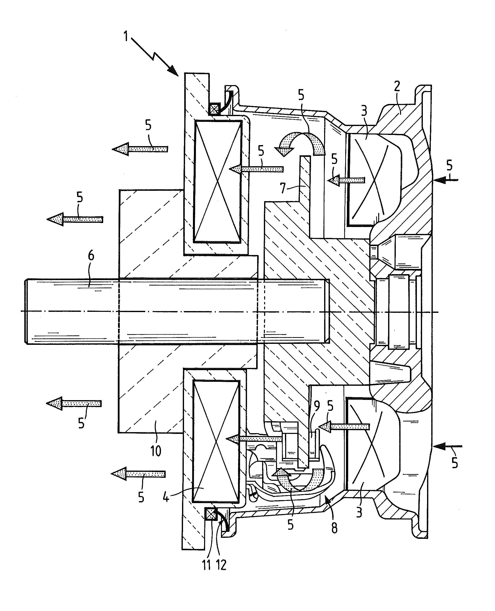
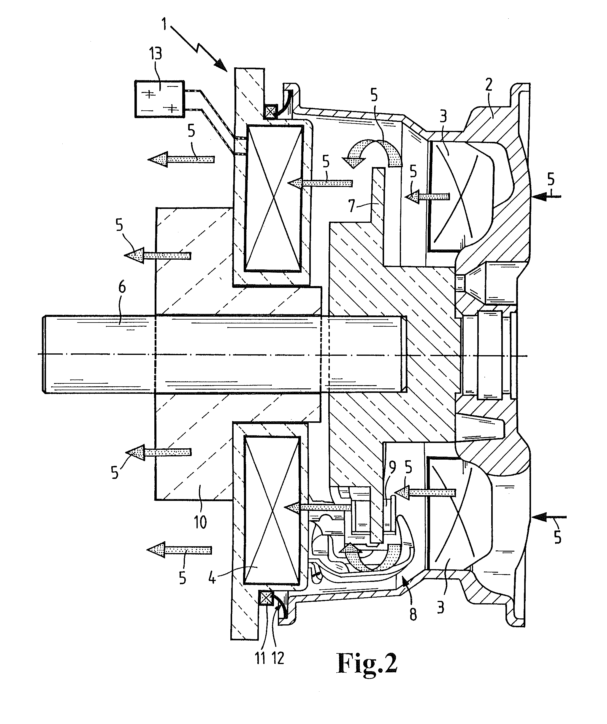
[0033]FIG. 1 shows a brake dust collecting device 1 for brake dust that is produced as abrasion of a motor vehicle disc brake. The brake dust collecting device 1 is received in the interior of a wheel rim 2 and includes fan blades 3 as well as a dust collecting unit in the form of a filter element 4. The fan blades 3 are located on the inner side of the wheel rim 2 that is facing the vehicle and are fixedly connected to the wheel rim. A plurality of such fan blades 3 are distributed about the circumference. The fan blades 3 have a flow-beneficial shape and generate an air flow 5 that is directed from the exterior to the interior and that passes through the openings in the wheel rim 2. The air flow 5 flows across the brake disc 7 against which the brake pads 9 applied by the brake caliper 8 are resting and transports the brake dust to the filter element 4 that is arranged stationarily on the vehicle. The filter element 4 is annularly shaped and is seated on a casing 10 of the wheel b...


PUM


Abstract

A brake dust collecting device for a motor vehicle has a dust collecting unit and an air flow generating device that generates an air flow that flows across brake parts of a motor vehicle wheel brake and that supplies brake dust of the wheel brake to the dust collecting unit. The air flow generating device has a rotatable fan blade and the dust collecting unit is a filter element.

Description

CROSS REFERENCE TO RELATED APPLICATIONS[0001]This application is a continuation application of international application No. PCT / EP2007 / 063460 having an international filing date of 6 Dec. 2007 and designating the United States, the International Application claiming a priority date of 8 Jan. 2007, based on prior filed German patent application No. 20 2007 000 246.7, the entire contents of the aforesaid international application and the aforesaid German patent application being incorporated herein by reference.TECHNICAL FIELD[0002]This disclosure relates to a brake dust collecting device for motor vehicles and, more particularly, to a brake dust collecting device including an air flow generating device for generating an air flow that flows past the brake parts of a motor vehicle wheel brake and carries brake dust of the wheel brake to a dust collecting unit.BACKGROUND OF THE INVENTION[0003]A collecting device for the brake dust that is produced in the motor vehicle wheel brake by ab...

Claims


Application Information

Patent Timeline
Patent Type & Authority Applications(United States)
IPC IPC(8): A47L9/10A47L5/00
CPCB60T3/00F16D65/0031B60T17/221B60T5/00
Inventor JESSBERGER, THOMAS
Owner MANN HUMMEL GMBH
Why Eureka
Try Eureka