
Method of detecting very low levels of analyte within a thin film fluid sample contained in a thin thickness chamber

a thin film fluid and detection method technology, applied in the field of detection of very low levels of analyte within thin film fluid sample contained in thin thickness chamber, to achieve the effect of preventing its diffusion

Inactive Publication Date: 2009-10-15
ABBOTT POINT CARE
View PDF44 Cites 31 Cited by
  • Summary
  • Abstract
  • Description
  • Claims
  • Application Information

AI Technical Summary

Benefits of technology

[0008]The blood plasma or serum sample is added to the chamber, and all of the TSH molecules in the sample will bind to the immobile substrate containing the capture antibodies, thereby immobilizing all of the molecules present in the sample. The thin (typically less then ten microns (10μ)) chamber thickness allows rapid vertical molecular diffusion so that the diffusion between the two layers of the thin chamber occurs rapidly, allowing all the molecules of the analyte to contact the capture antibody surface. Ideally, the plasma, or other biological fluid being examined, should be clear and free of particles such as cells that might interfere with the binding of analyte or the detection of signal in the assay.
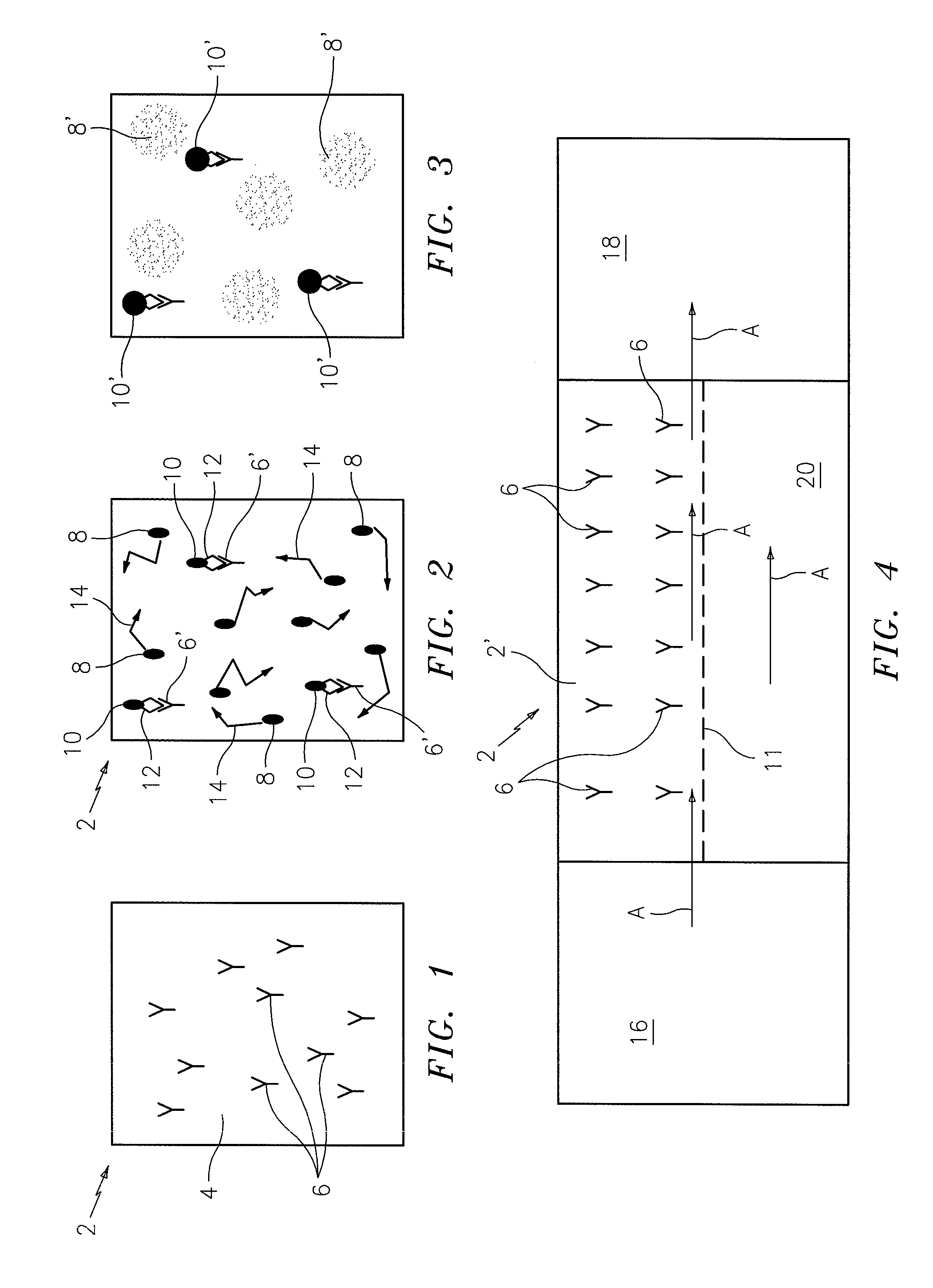
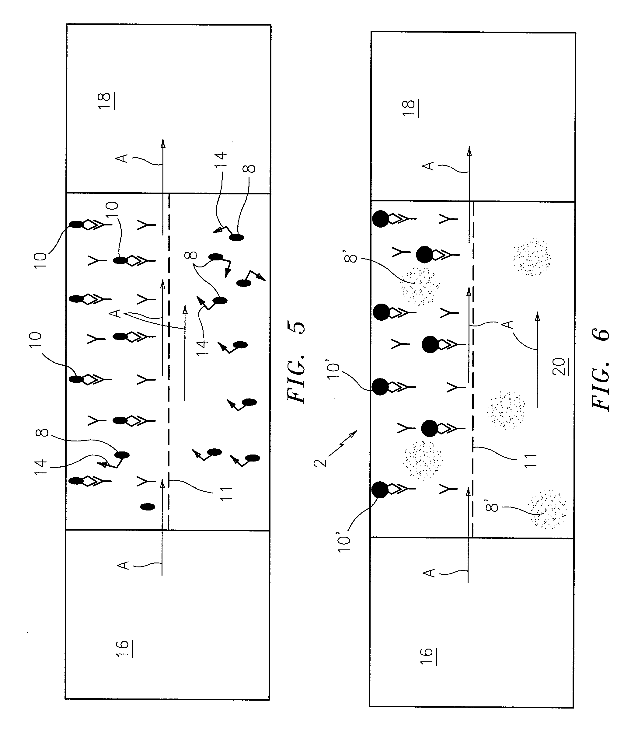
[0010]A single fluorescent nanoparticle containing an antibody / ligand directed against the second epitope of the TSH analytes will attach to each TSH molecule that is bound to the substrate. Those fluorescent nanoparticles that are not immobilized by virtue of their attachment to the immobilized analyte will continue to be in colloidal suspension and move due to Brownian motion. To distinguish bound nanoparticles from unbound nanoparticles, the test chamber is imaged under appropriate fluorescent illumination, in the focal plane of the bound particles, after incubation for a period of time which is long enough to give a measurable rise in signal due to the immobile light emitting nanoparticles, as compared to the emission of the moving light emitting nanoparticles which will cause background light due to unbound signal generating nanoparticles. This time of exposure may be adaptively determined by the measuring instrument but limited in its upper extent since it is possible that the areas may have no bound nanoparticles. Those nanoparticles which remain in one location because they are fixed to the substrate will put all of their photons into just a few pixels, while those which “dance” around due to Brownian motion will distribute their brightness over a much larger area, thereby making the detection of the immobile particles possible. A surface area of the chamber which is free of capture antibodies can serve as the control area.
[0011]Using this technique, the concentration of nanoparticles in the imaged area should be small enough so that they do not completely overlap and diminish the ability of the sensor to distinguish the immobile particles. The number of individual distinguishable immobile fluorescent particles is therefore equal to the number of molecules of the target analyte contained in the volume of the chamber above or below the capture antibodies within the capture area. Since the volume of the fluid above the control area is relatively small compared to the volume above the immobilized capture antibody or ligand, it may be ignored for purposes of calculating the total volume of the chamber or narrow passage, acting as a diffusion barrier separating the control area from the capture area which may be used to obtain an exact chamber volume over the capture area. Alternatively, an actual impermeable barrier may be employed to separate the capture area from the control area. The maximum number of molecules that may be measured in the contained sample is defined by the capture area of the chamber and the pixel magnification. The concentration of the target analyte will be the number of molecules detected divided by the sample contents in the chamber above the capture area. The volume of the chamber is defined by the known height of the chamber and the area of the sample, which may be defined by the number of pixels within the sample area and the area / pixel magnification factor. Therefore, if the chamber height and magnification are known, the amount of sample volume may also be determined by the instrument performing the analysis. It is necessary that the bound molecules be bound a sufficient distance from each other so that coincidence of signal from the captured labeled nanoparticles avoided. For example, if the fluorescence of a signal contained on a nanoparticle can be detected over an area of 3 to 10 pixels, and the desired image separation of the nanoparticles is at least twice that distance, or about 15 pixels apart, with a magnification yielding an image size of 0.5 microns / pixel, a one square cm of sample area would contain enough resolution for the detection of maximum of about one to two million molecules per chamber. The lower limit of the amount of molecules detected in the chamber is in theory, one, limited of course, by counting statistics. It will be appreciated by one skilled in the art that the thinner the chamber, the greater the discrimination between bound from free labeled target analyte ligand, but the smaller the volume of the sample contained in the chamber. The larger the area of the chamber, the greater the dynamic range, but the longer the time needed to obtain the images of the chamber for analysis.

Problems solved by technology

The first and second type epitopes must be spatially located on the target analytes so that the binding of one epitope does not prevent the binding of the second epitope.

Method used


Image

  • Method of detecting very low levels of analyte within a thin film fluid sample contained in a thin thickness chamber
  • Method of detecting very low levels of analyte within a thin film fluid sample contained in a thin thickness chamber
  • Method of detecting very low levels of analyte within a thin film fluid sample contained in a thin thickness chamber

Examples


Embodiment Construction

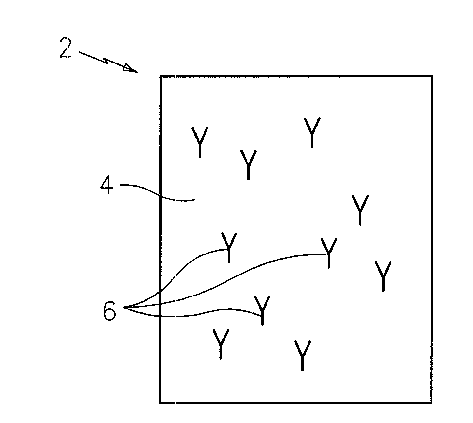
[0022]Referring now to FIG. 1 there is shown a portion of a thin film test sampling chamber which is denoted generally by the numeral 2. The test sample being assayed in this case is blood plasma or serum and it is being assayed for the presence of TSH (Thyroid Specific Hormone). The chamber 2 has a surface or wall 4 to which a plurality of ligands 6 is affixed. In this case the ligands 6 will be specific to a first surface epitope of the TSH molecules being assayed.

[0023]FIG. 2 shows the chamber 2 after it has been filled with a mixture of the plasma being assayed and fluorescent reporter particles 8. The particles 8 include ligands that are specific to a second epitope on the target analyte so that some of the particles will bond with target analyte molecules prior to being placed in the testing chamber 2. Fluorescent reporter particles that bond to the target analyte molecules 12 are designated by the numeral 10. The free unbound fluorescent reporter particles are designated by t...


PUM


Abstract

A method and apparatus for the detection and quantification of very low levels of a target analyte using an imaging system is provided. In the case of some analytes such as certain hormones, for example TSH, their levels may be as low as several tens of thousands of molecules per micro liter. These extremely low levels can be measured by using the present invention to count the individual molecules of analyte. The invention also has the advantage of being a primary quantitative method, which is one which needs no standardization.

Description

[0001]This application claims the benefit of U.S. Provisional Application No. 61 / 043,571, filed Apr. 9, 2008.BACKGROUND OF THE INVENTION[0002]1. Technical Field[0003]This invention relates to a method and apparatus for the detection and quantification of very low levels of a target analyte using an imaging system such as that disclosed in U.S. Pat. No. 6,929,953. In the case of some analytes such as certain hormones, for example TSH, their levels may be as low as several tens of thousands of molecules per micro liter. These extremely low levels can be measured by using the present invention to count the individual molecules of analyte. The invention also has the advantage of being a primary quantitative method, and therefore does not need standardization.SUMMARY OF THE INVENTION[0004]The method is for the detection and quantification of a defined target analyte disposed, for example, as a thin film biological fluid sample contained in a thin thickness planar chamber typically from a...

Claims


Application Information

Patent Timeline
IPC IPC(8): G01N33/53
CPCB82Y15/00G01N33/588G01N33/54366
Inventor WARDLAW, STEPHEN C.LEVINE, ROBERT A.
Owner ABBOTT POINT CARE
Learn More