
Vacuum driven bulk resin unloading apparatus and method

a vacuum-driven, bulk resin technology, applied in the direction of loading/unloading, bulk conveyors, transportation and packaging, etc., can solve the problems of inefficient vacuum-driven loaders, inconvenient rotation, and affecting the rotational movement of containers, so as to facilitate rotational movement

Inactive Publication Date: 2009-10-15
MAGUIRE STEPHEN B
View PDF18 Cites 8 Cited by
  • Summary
  • Abstract
  • Description
  • Claims
  • Application Information

AI Technical Summary

Benefits of technology

[0014]A motor is coupled to the plate and is adapted to slide with the plate along the longitudinal axis of the extension assembly. The motor also engages the second tube, preferably by a pulley assembly, so as to cause the second tube to rotate in one direction at least 360 degrees, but, preferably, the second tube is adapted to rotate continuously either clockwise or counterclockwise without rotational limitations. To this end, the motor facilitates the rotational movement of both the second tube and the attached flexible tube.

Problems solved by technology

However, usually these containers are too heavy to be lifted by a person and a mechanical means is necessary to remove the contents.
To this end, without operator assistance to reposition the lance or wand, the vacuum loader is inefficient to remove all of the particulate material and may leave as much as half the contents within the container.
This is very costly in terms of labor and lost production.
In other words, it is limited to a sack or sack-like container and does not provide a solution for evacuating resin from more rigid container types, e.g. drums, barrels, gaylords, bulk truck, rail cars, silo, day bins, flat bottom bins, or other utility bins.

Method used


Image

  • Vacuum driven bulk resin unloading apparatus and method
  • Vacuum driven bulk resin unloading apparatus and method
  • Vacuum driven bulk resin unloading apparatus and method

Examples


Embodiment Construction

[0034]The present invention relates to an apparatus and method for unloading the contents of a container. More specifically, the present invention utilizes the suction force created from a vacuum pump to remove particulate material or bulk resin stored within a container. The material may be comprised of plastic resin, plastic pellets, powder, and any other similar type of substance, which is known to be stored in containers. The apparatus and method of the present invention is applicable to any type of storage or transport container known in the art such as, gaylords, drums, barrels, bulk trucks, rail cars, silo, day bins, flat bottom bins or other utility bins which may or may not have a sloped bottom or flat bottom; however, the apparatus and method of the present invention is preferably used on Gaylord style containers.

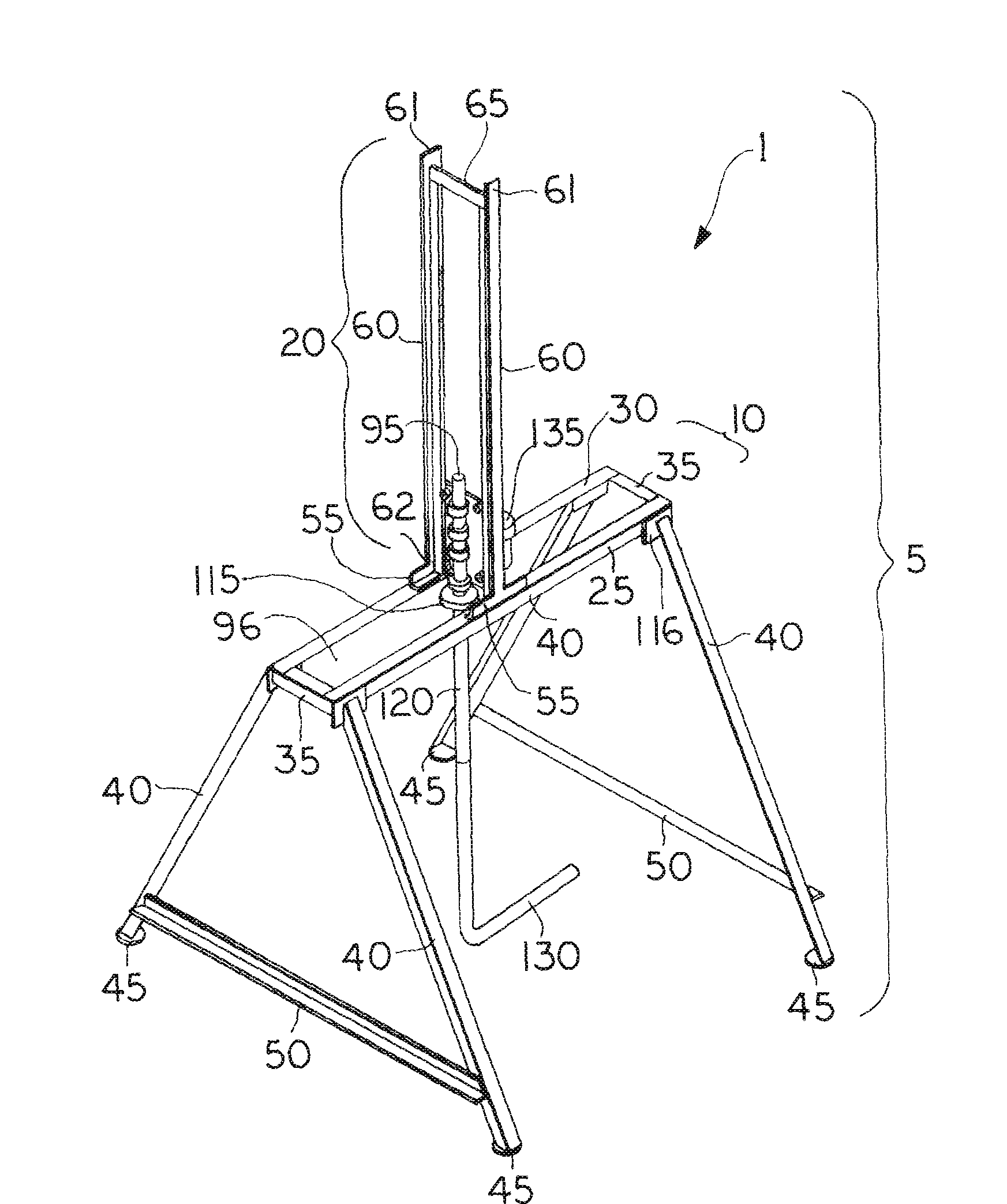
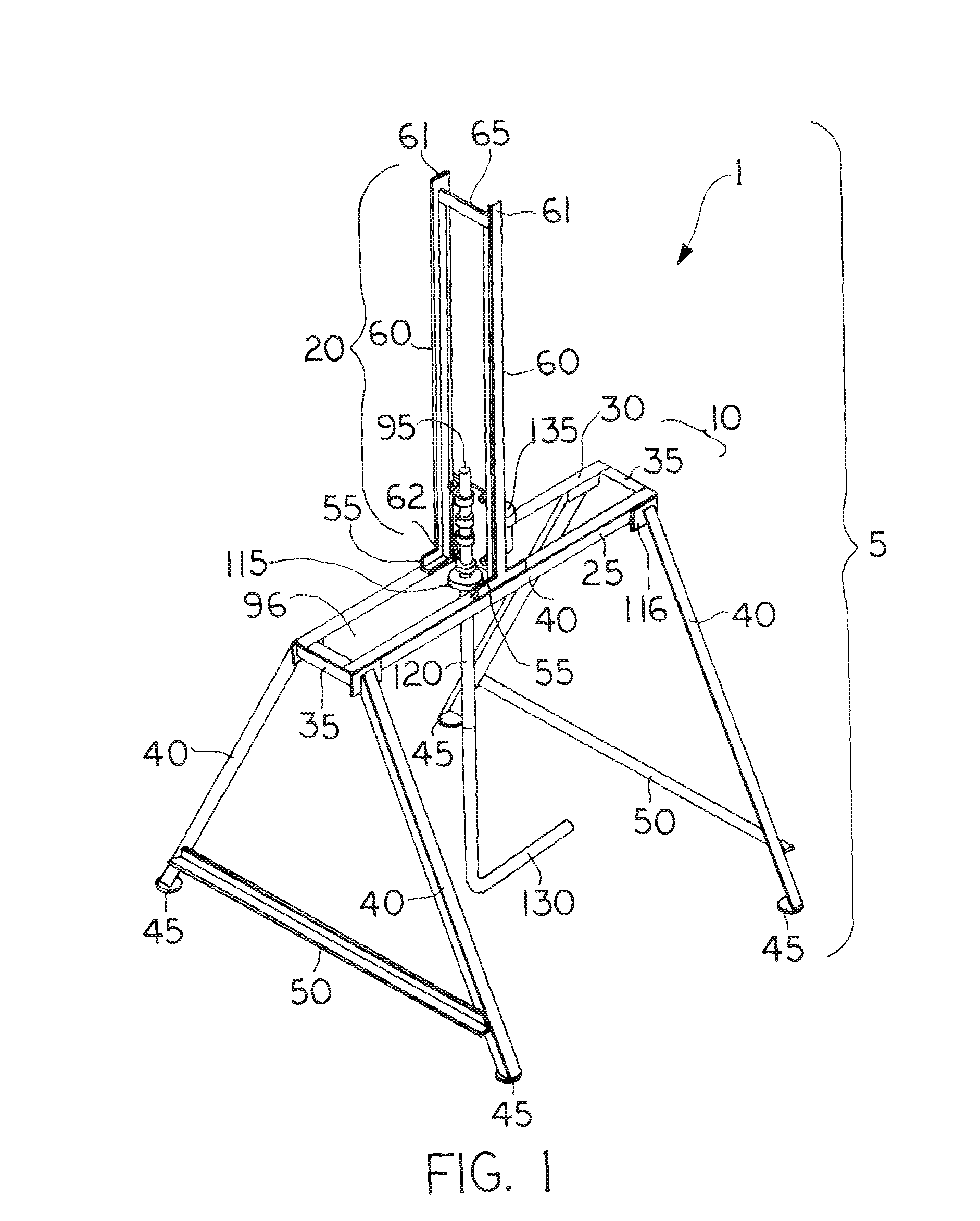
[0035]Referring to FIG. 1, the vacuum loader assembly 1 of the present invention is illustrated. At its core, the vacuum loader assembly 1 is comprised of a frame...


PUM


Abstract

The present invention relates to a vacuum loader assembly wherein the assembly is comprised of a frame, a first and second tube, a flexible tube, a motor, and a sweeper assembly. The frame is adapted to be positioned over an opening of the container. The first tube is mounted to the frame and is in fluid communication with a vacuum source. The second tube is rotatably mounted to the first tube and is also in fluid communication with the first tube and the sweeper assembly is mounted to the second tube. The flexible tube extends from the second tube such that, when the frame of the present invention is placed over a container, the second tube, flexible tube, and sweeper assembly are lowered into the container and rotated by the motor such that, when the vacuum source is activated, the flexible tube suctions out the contents of the container.

Description

FILED OF THE INVENTION [0001]The present invention relates to an apparatus and method for unloading the contents of a container. More specifically, the present invention relates to an apparatus which utilizes the suction force created from a vacuum pump to remove substantially all of the particulate material or bulk resin stored within a container without an operator's intervention.BACKGROUND OF THE INVENTION [0002]In many manufacturing operations, particularly with respect to plastic fabrication, it is not uncommon for some of the materials that are employed in the operation to be shipped to the manufacturing facility in heavy containers, e.g. drums, barrels, gaylords, bulk truck, rail cars, silo, day bins, flat bottom bins, or other utility bins which may or may not have a sloped bottom or flat bottom. Drums are typically fiber drums that are typically cylindrical, but can be other shapes as well, and usually hold between 200 to 250 lbs of material. Barrels can be the traditional ...

Claims


Application Information

Patent Timeline
IPC IPC(8): B65G53/54
CPCB65G65/36B65G53/42
Inventor MAGUIRE, STEPHEN B.
Owner MAGUIRE STEPHEN B
Learn More