Sludge Treatment System for Dam
- Summary
- Abstract
- Description
- Claims
- Application Information
AI Technical Summary
Benefits of technology
Problems solved by technology
Method used
Image
Examples
Embodiment Construction
[0054]This invention will be described further by the way of exemplary embodiments with reference to the accompanying drawings.
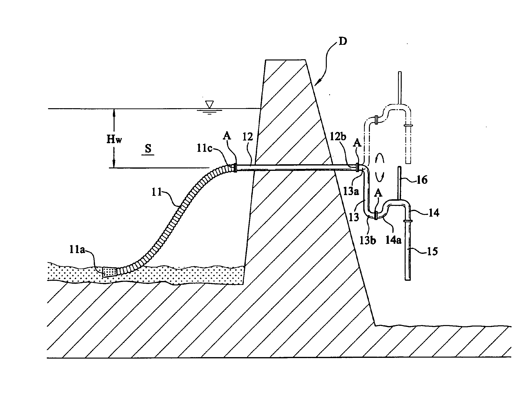
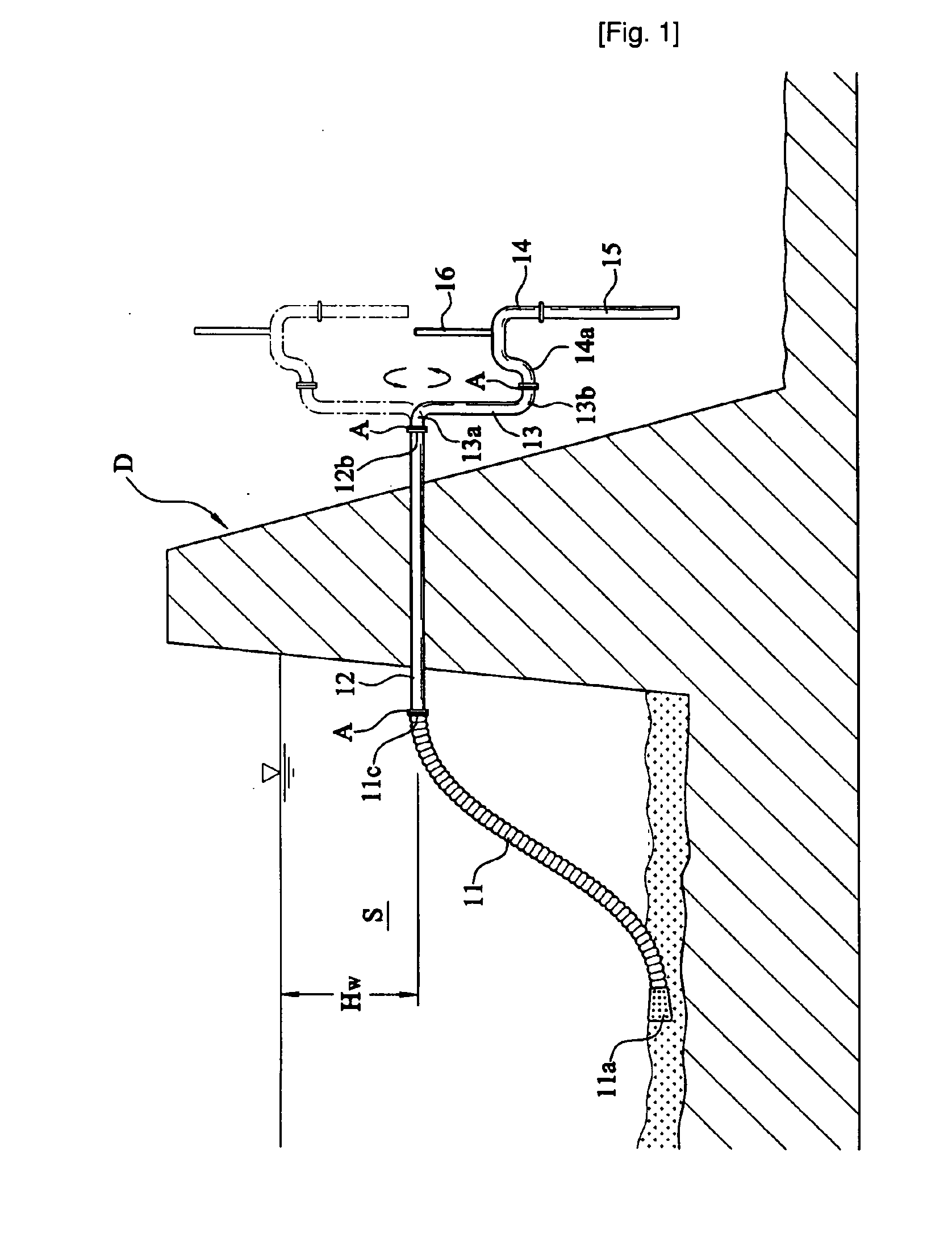
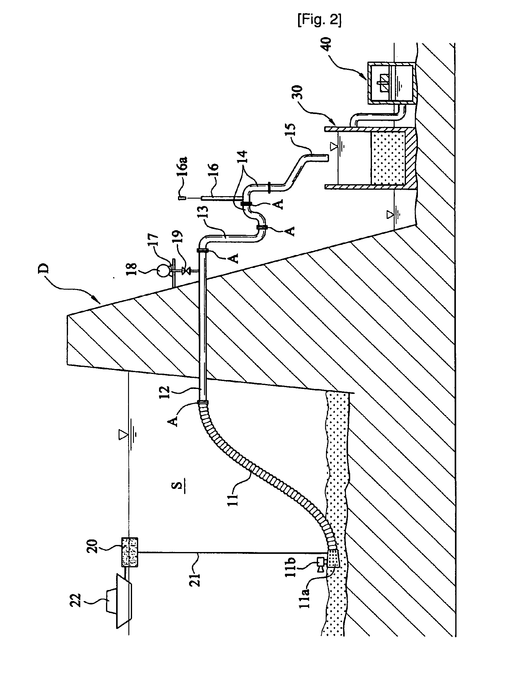
[0055]FIGS. 1 and 11 show a sludge treatment system for a dam according to the present invention. An induction pipe 11, a dam passage 12, an induction force action pipe 13, an air control pipe 14 and a drain pipe 15 are sequentially connected, which forms a channel for siphoning the sediment on the floor of a body of water retained by a dam “D” and for discharging the sediment toward the outside of the dam “D”. A pipe joint “A” is present at each coupling between the induction pipe 11, the dam passage 12, the induction force action pipe 13 and the air control pipe 14. Each pipe can be rotated by the pipe joint “A”. An air vent pipe 16 is connected at the top flat portion of the air control pipe 14 and dissipates the induction action of both the air control pipe 14 and the drain pipe 15.
[0056]The dam passage 12 penetrates through the dam “D” halfway up the he...
PUM
| Property | Measurement | Unit |
|---|---|---|
| Pressure | aaaaa | aaaaa |
| Power | aaaaa | aaaaa |
| Size | aaaaa | aaaaa |
Abstract
Description
Claims
Application Information
 - R&D
- Intellectual Property
- Life Sciences
- Materials
- Tech Scout
- Unparalleled Data Quality
- Higher Quality Content
- 60% Fewer Hallucinations
Browse by: Latest US Patents, China's latest patents, Technical Efficacy Thesaurus, Application Domain, Technology Topic, Popular Technical Reports.
© 2025 PatSnap. All rights reserved.Legal|Privacy policy|Modern Slavery Act Transparency Statement|Sitemap|About US| Contact US: help@patsnap.com


