
Image generation method and device for emission computed tomography

a computed tomography and image generation technology, applied in tomography, radiography controlled devices, instruments, etc., can solve the problems of long measurement time, inability to execute effective patient motion compensation, and difficulty in obtaining compensation effect of patient motion, etc., and achieve the effect of short tim

Inactive Publication Date: 2009-10-01
HITACHI LTD
View PDF11 Cites 20 Cited by
  • Summary
  • Abstract
  • Description
  • Claims
  • Application Information

AI Technical Summary

Benefits of technology

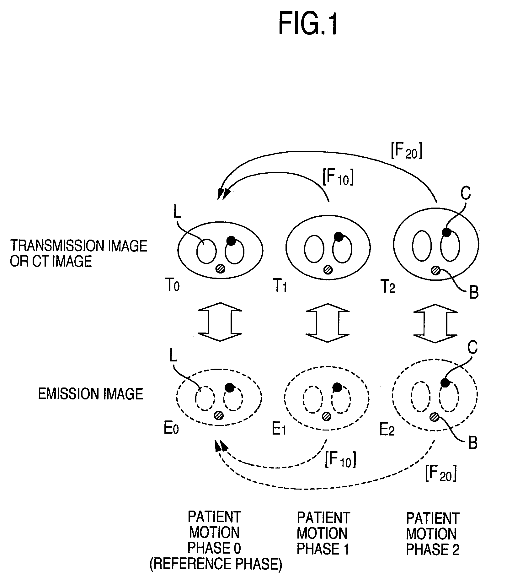
[0013]In The Journal of Nuclear Medicine, Vol. 45, No. 2, pages 214 to 219, it has been described that it is possible to enhance statistical accuracy, by superimposing E image information obtained by gated-acquisition on image information of a certain determined phase with non-linear deformation, and superimposing pixel values. However, in The Journal of Nuclear Medicine, Vol. 45, No. 2, pages 214 to 219, there is no recognition of difficulty in deforming E image information and superimposing each other. Different from morphological image of image information to be reconstructed by X-ray CT, and T image information etc., E image information does not intend to draw a structure inside a body. Therefore, it is generally extremely difficult to deform E image information by each of patient motion phases and superimpose it each other.
[0014]It is an object of the present invention to provide an image information preparation method enabling to provide more vivid functional image information of a living body with a target of a moiety receiving impact of patient motion, in a short time.
[0016]According to the present invention, more vivid functional image information of a living body can be obtained, in a short time, with a target of a moiety receiving impact of patient motion.

Problems solved by technology

However, in order to obtain data with sufficient statistical accuracy by each patient motion phase, a long measurement time is required.
However, it increases patient motion within one patient motion phase time, and in the first place, it is difficult to obtain compensation effect of patient motion.
That is, in a simple gated-acquisition, it cannot be executed effective patient motion compensation actually in a short time, and problems of (1) blurring of E image information and (2) decrease in quantitativeness of E image information cannot be solved basically.
Therefore, it is generally extremely difficult to deform E image information by each of patient motion phases and superimpose it each other.

Method used


Image

  • Image generation method and device for emission computed tomography
  • Image generation method and device for emission computed tomography
  • Image generation method and device for emission computed tomography

Examples


embodiment 1

[0025]As impacts given by respiratory motion on E image information, there are the following three:[0026](1) blurring of E image information[0027](2) decrease in quantitativeness of E image information[0028](3) position mismatch in superimposing X-ray CT image taken under breath-holding and PET image, at the peripheral of a lung field

[0029]The problems (1) and (2) among these have become main concerns as large factors impairing picture quality at present with dramatic enhancement of spatial resolution of the PET device. As for the problem (3), even at present with frequent experience of superimposing image information by the recently developed combined PET / CT device (refer to The Journal of Nuclear Medicine, Vol. 45, No. 1, pages 4S to 14S), solution thereof is still highly desired mainly in a field requiring specification of position of malignant tumor in good accuracy, such as in radiation therapy and biopsy.

[0030]The problem of (1) makes difficult radiation therapy planning and e...

embodiment 2

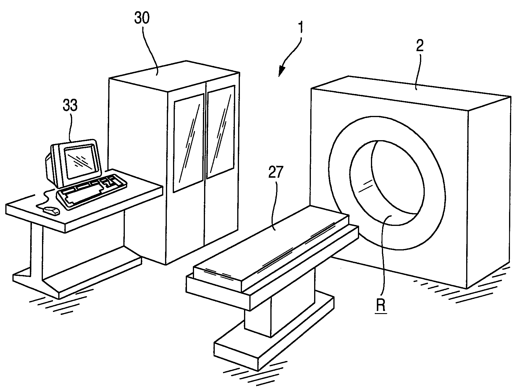
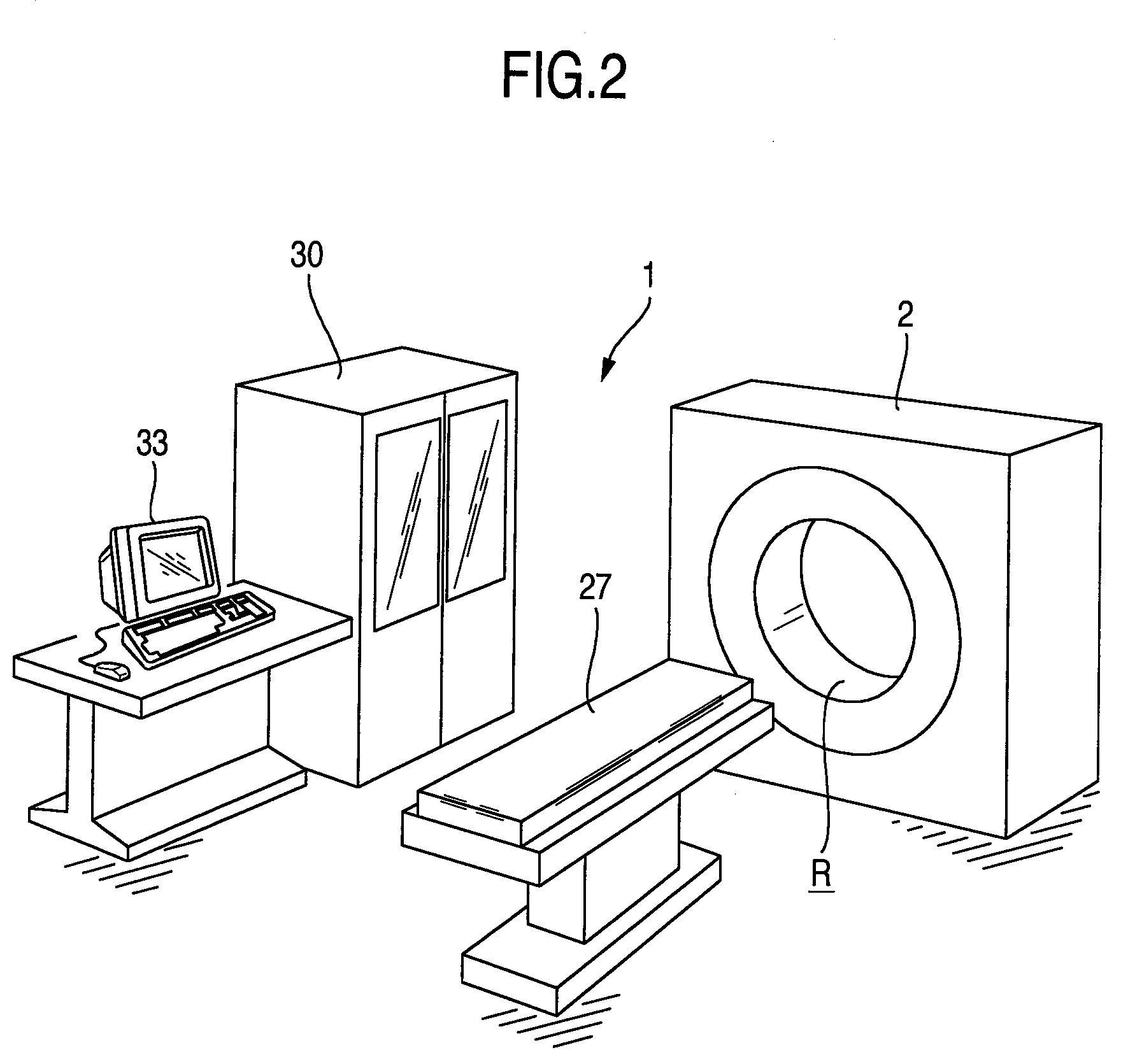
[0062]Explanation will be given on a positron emission computed tomography device 1 (the PET device), which is one suitable embodiment of the present invention, with reference to FIG. 2 to FIG. 7. FIG. 2 is a schematic configuration drawing of a positron emission computed tomography device of one embodiment. The PET device of the present embodiment, as shown in FIG. 2, has provided with a computed tomography device 2, a bed 27 for supporting a patient 29, a data processing device 30 and a display device 33.

[0063]The computed tomography device 2 has a housing 45 (refer to FIG. 4) encompassing a measurement space R, and a plurality of detector units 6 arranged so as to encompass the measurement space R (refer to FIG. 3 and FIG. 4). These detector units 6 are held by a unit support member 3 installed at the housing 45 arranged by encompassing the measurement space R. These detector units 6 are inserted inside a plurality of opening parts 4 installed at the unit support member 3 and arr...


PUM


Abstract

A first γ-ray generating in a body, caused by a PET pharmaceutical, and a second γ-ray emitted from a γ-ray source and transmitting through the body are detected with a radiation detector. The emission image information (E image information), E1, E1 and E2, at each of patient motion phases, 0, 1 and 2, which divided a respiration period, are prepared by using each information obtained from the detected first γ-ray. The transmission image information (T image information), T0, T1 and T2, at each of patient motion phases, 0, 1 and 2, respectively, are prepared, by using each information obtained from the detected second γ-ray. Relative displacements, ([F10], [F20]), are determined by superimposing, on T image information T0, other T image information, T1 and T2. The E image information, E1, E2, are superimposed on the E image information E0, by using this relative displacement.

Description

BACKGROUND OF THE INVENTION[0001]The present invention relates to a preparation method for image information by an image processing device.[0002]A PET device has been used, as an important tool, mainly in an object of diagnosis of malignant tumor in a medical field, in recent years. The PET device measures radiation (γ-ray) emitted from the inside of a patient body, derived from a radiopharmaceutical injected into a patient as a subject body, and images distribution of the radiopharmaceutical in the patient body from measurement data thereof. Such a PET device is used in diagnosis of metabolic function and physiologic function. As a typical radiation image diagnosis device, which applies radiation measurement technology, for non-invasively obtaining image of the inside of the patient, there is an X-ray CT device.[0003]The PET device is equipped with many radiation detectors, and is required to process a huge amount of radiation detection signals (γ-ray detection signals), which are ...

Claims


Application Information

Patent Timeline
Patent Type & Authority Applications(United States)
IPC IPC(8): G01T1/166G01T1/24H05G1/60
CPCA61B5/113A61B6/541A61B6/037A61B6/032
Inventor KOBASHI, KEIJITAKEUCHI, WATARU
Owner HITACHI LTD
Learn More