Method for making castings by directed solidification from a selected point of melt toward casting periphery

Inactive Publication Date: 2009-10-01
ANISIMOV OLEG VLADIMIROVICH +1
View PDF2 Cites 1 Cited by
  • Summary
  • Abstract
  • Description
  • Claims
  • Application Information

AI Technical Summary

Benefits of technology

[0012]The present invention is aimed at resolving a technical problem, which consists in developing a method for making castings in a mold by setting up and maintaining a melt solidification front directed from a selected point within the melt toward the casting periphery in order to improve the strength characteristics of the casting and achieve isotropy of its properties.

Problems solved by technology

In this environment, the two-phase solidification front zone forming at the casting periphery obstructs removal of latent heat as it moves toward the center at a slowing rate, causing variation in the grain size and raising pressure within the melt as the contracting solid phase grows, and in this way provoking the release of dissolved gases into the melt.
This organization of the solidification process is ineffective, to an extent, and results, no matter what option is used, in the casting grain size developing a gradient and hence anisotropy of properties.
Moreover, when solidification is effected by heat removal, defects such as micro- and macro-voids and various forms of liquation cannot be avoided.
Use of alloys, as also addition of a modifier to complete volume solidification to produce a fragmented structure gives rise to several problems.
Also, excessive pressure is produced within the melt, for example, in a thermostatic gas chamber.
Since, however, excessive pressure is built in all examples within the entire volume of the melt, and heat is removed, as it has been before, from the surface, the solidification front is directed from the periphery to the center, causing all possible casting defects typical of prior art methods.
Indeed, the solid peripheral phase, like the solidification front as well, shuts off the accompanying gas phase inside, contributing to blistering, cracking, liquation, and so on.
To put this method into practice, however, a high pressure is to be built up with the possibility of the casting mold containing the melt being broken.
Moreover, the constant rotation speed of the mold to produce the desired pressure results in anisotropy of the casting structure and strength characteristics because the solidification front shifts as overcooling decreases continuously toward the rotation axis of the mold.

Method used


Image

  • Method for making castings by directed solidification from a selected point of melt toward casting periphery
  • Method for making castings by directed solidification from a selected point of melt toward casting periphery
  • Method for making castings by directed solidification from a selected point of melt toward casting periphery

Examples


Embodiment Construction

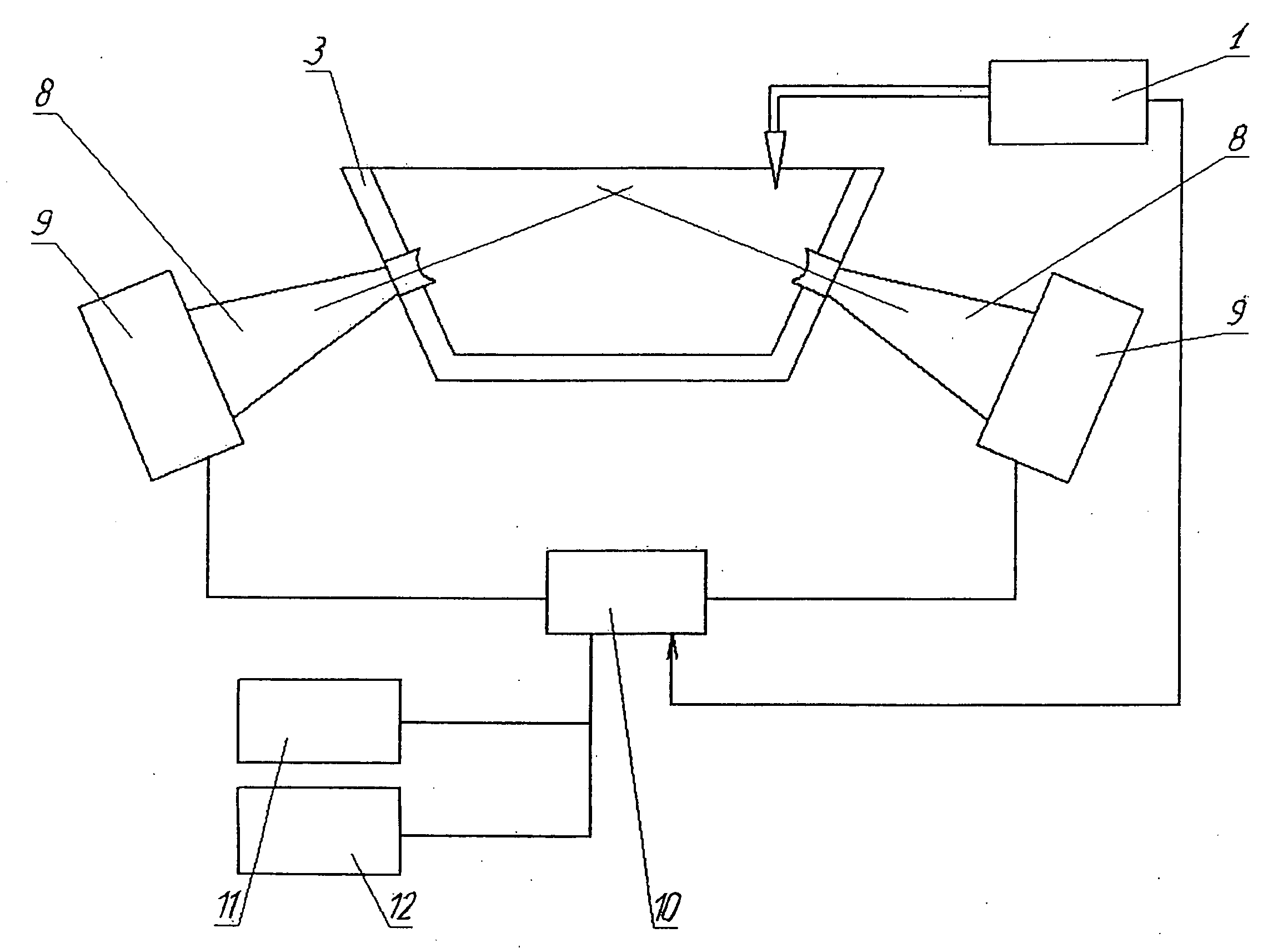
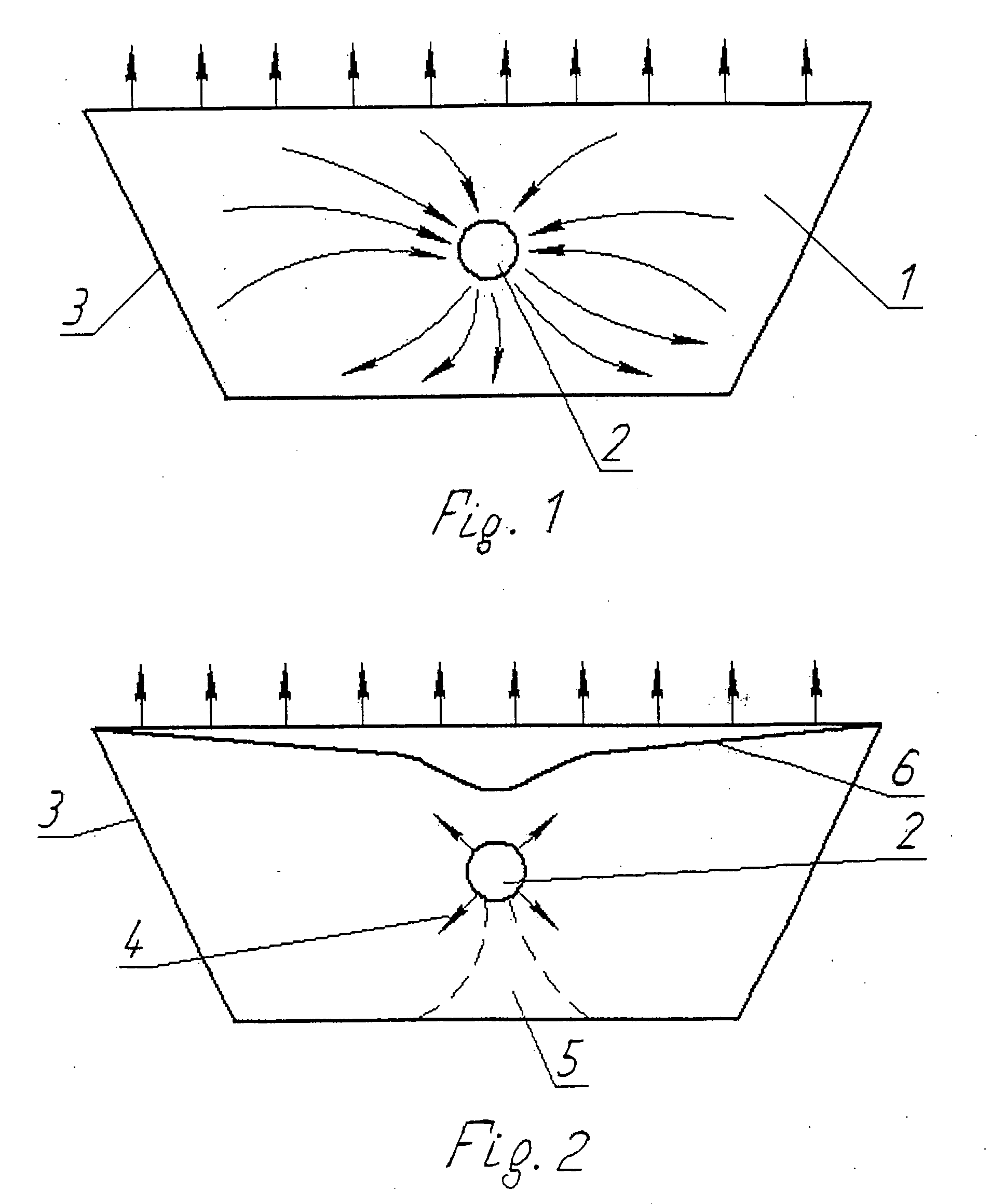
[0024]In principle, a directed solidification method consists in making use of a physical phenomenon that can control reduction in the energy state of a melt to a level where solidification begins. Until recently, practically all solidification control methods have been confined to influencing the thermal processes occurring in the melt. To do so, apparatuses maintaining desired temperature gradients in the melt were used for solidification control purposes. Directed heat removal at desired intensity allows preferred conditions to be created for initiating solidification in a desired zone of the melt, which is actually the most widespread form of directed solidification. This directed solidification option is effective enough if applied to castings of small size. This limitation is explained by the fact that the temperature field within the melt is distorted during melt solidification, releasing latent solidification heat in the process, that is, it distorts (reduces) the temperatur...


PUM

PropertyMeasurementUnit
Cooling rateaaaaaaaaaa
Temperatureaaaaaaaaaa
Forceaaaaaaaaaa

Abstract

The invention is related to the foundry practice. According to this invention, the method for making castings by directed solidification from a selected point of the melt toward the periphery of the casting comprises forming a casting in a mold having thermodynamic characteristics that allow uniform volume cooling of the melt to be effected to a temperature at which natural solidification processes are completed. To improve the structural isotropy of the casting formed, the cooling is effected at a rate not exceeding 0.5° C. / sec. The casting is formed in a nonuniform field of force. The nonuniform field of force is set up by ultrasonic waves focused on a selected point of the melt to form therein a localized elevated pressure zone and to direct the solidification front from the zone toward the periphery of the casting. The nonuniform field of force is sustained in the mold until the cooling casting reaches a temperature at which the natural melt solidification processes are completed as the melt cools. Before the melt is poured into the mold, it is overheated to a level that, together with the thermodynamic characteristics of the mold allowing the melt therein to be cooled at a rate not exceeding 0.5 K / sec, sustains the liquid phase of the melt for a time sufficient for directed melt solidification to be effected from the selected point of the melt toward the periphery of the casting before the commencement of natural melt solidification processes as the melt cools. Subsequently, as the temperature at which natural solidification processes are completed is reached, the nonuniform field of force is removed, and casting cooling may continue at any reasonable rate.

Description

CROSS REFERENCE TO RELATED APPLICATIONS[0001]Applicants claim priority under 35 U.S.C. §119 of Russian Application No. 2008111707 filed on Mar. 27, 2008.FIELD OF THE INVENTION[0002]The invention is related to the foundry practice, and particularly to methods for making castings by directed solidification of the melt.BACKGROUND OF THE INVENTION[0003]The need to effectively control solidification of a metal melt in a mold to make castings with acceptable practical service properties forces researchers and engineers to look constantly for new approaches in order to radically improve the quality of castings because castings acquire their basic service properties at the crystalline structure solidification stage.[0004]Until recently, all methods for controlling processes developing during solidification of metal melts have been confined to influencing the thermal processes within the melt and at the heat exchange boundary. In this environment, the two-phase solidification front zone form...

Claims


Application Information

Patent Timeline
IPC IPC(8): B22D27/04B22D27/08
CPCB22D27/045
Inventor ANISIMOV, OLEG VLADIMIROVICHSHTANKIN, YURY VALERYEVICH
Owner ANISIMOV OLEG VLADIMIROVICH
Why Eureka
Try Eureka