Packing box for wellhead of pumping unit

A technology for pumping wells and packing boxes, which is applied in wellbore/well parts, sealing/packing, earthwork drilling and production, etc. It can solve the problems of increased production cost, reduced oil recovery efficiency, and shortened service life of packing, achieving The effect of reducing the frequency of replacing the sealing packing, improving oil production efficiency, and avoiding oil leakage

Active Publication Date: 2020-10-16
东营利达石油工程技术服务有限公司
View PDF11 Cites 0 Cited by
  • Summary
  • Abstract
  • Description
  • Claims
  • Application Information

AI Technical Summary

Problems solved by technology

[0003] 1. The packing boxes are all installed outdoors, and the wind and sand adhere to the surface of the polished rod, and enter between the packing and the polished rod with the polished rod, so that sand grinding is formed between the polished rod and the packing, which accelerates the wear speed of the packing, and the packing and the polished rod There will be gaps between oil leaks soon, and the service life of the packing is very short. It is necessary to stop the pumping unit frequently to replace the packing, which will cause the oil well to stop production for a short time, increase the number of operations and stop time, reduce the oil production efficiency, and reduce the production efficiency. Increased costs
[0004] 2. After soaking the packing in lubricating oil, take it out and install it in the packing box to reduce the friction between the packing and the polished rod. However, the lubricating oil in the packing will gradually decrease when the polished rod moves up and down , so that dry grinding is formed between the packing and the polished rod, resulting in faster wear of the packing and shortening the service life of the packing

Method used


Image

  • Packing box for wellhead of pumping unit
  • Packing box for wellhead of pumping unit
  • Packing box for wellhead of pumping unit

Examples


Embodiment Construction

[0024] The following will clearly and completely describe the technical solutions in the embodiments of the present invention with reference to the accompanying drawings in the embodiments of the present invention. Obviously, the described embodiments are only some, not all, embodiments of the present invention. Based on the embodiments of the present invention, all other embodiments obtained by persons of ordinary skill in the art without making creative efforts belong to the protection scope of the present invention.

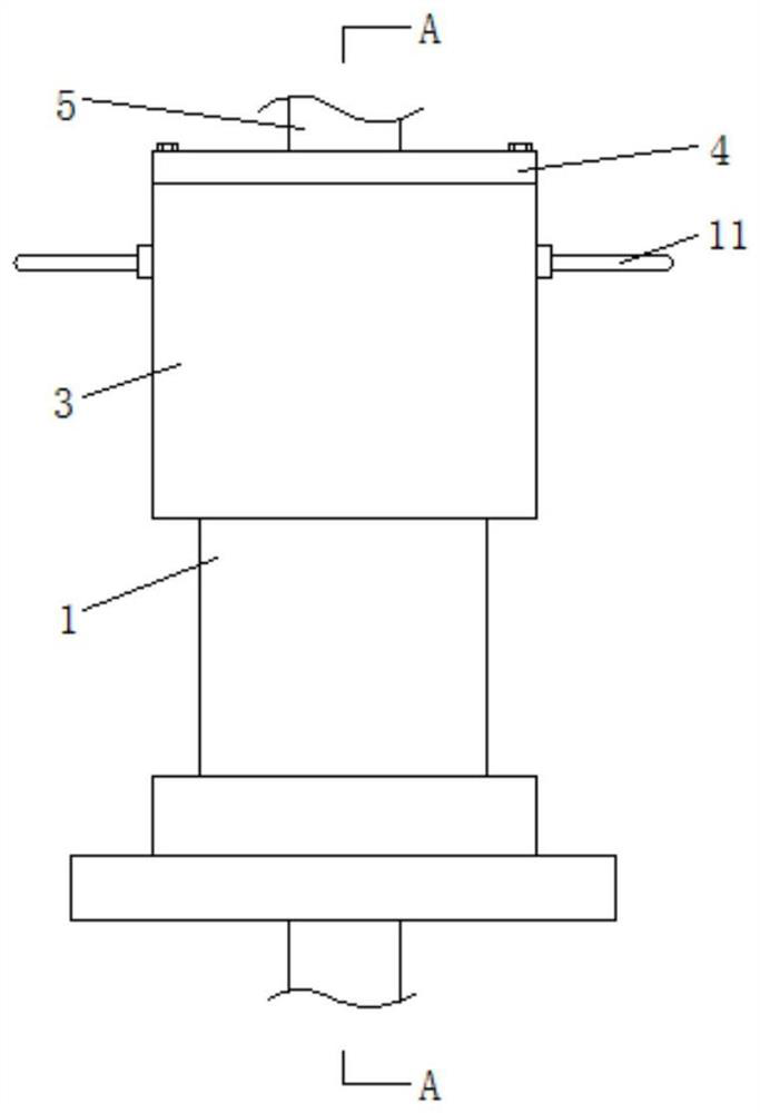
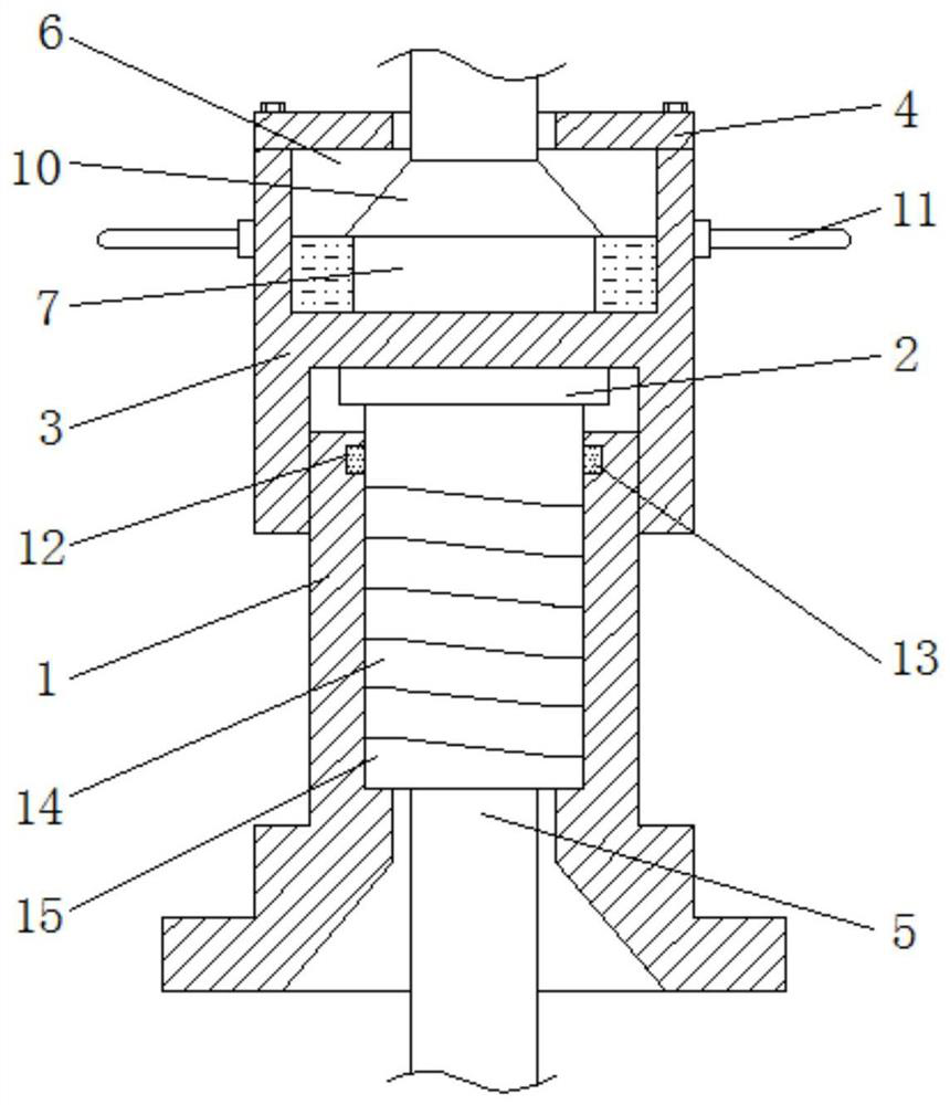
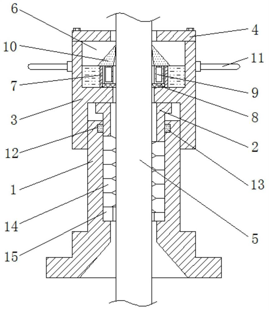
[0025] see figure 1 -5, a packing box for the wellhead of a pumping unit, including a box body 1, a gland 2 is provided on the top of the inner cavity of the box body 1, a gland 3 is arranged on the top of the box body 1, and the gland 3 is arranged on the top of the box body 1. The top of the cover 3 is provided with a cover plate 4, the top of the cover plate 4 is provided with a polished rod 5, and the bottom end of the polished rod 5 runs through the cover...


PUM


Abstract

The invention relates to the technical field of oilfield exploitation equipment, and discloses a packing box for an oil pumping unit wellhead. The packing box for the oil pumping unit wellhead comprises a box body, a pressing sleeve is arranged at the top of an inner cavity of the box body, a pressing cover is arranged at the top of the box body, a cover plate is arranged at the top of the pressing cover, a polish rod is arranged at the top of the cover plate, the bottom end of the polish rod sequentially penetrates through the cover plate, the pressing cover, the pressing sleeve and the box body, and a storage cavity is formed in the pressing cover. The top of the inner wall of sand scraping rubber is attached to the surface of the polish rod by arranging a taper hole in the sand scrapingrubber, then, the sand scraping rubber can scrape sand gravel on the surface of the polish rod when the polish rod moves downwards, the problems that the abrasion rate of sealed packing is accelerated due to the fact that the sand gravel moves following the polish rod to enter between sealed packing and the polish rod, and sanding is formed between the sealed packing and the polish rod are solved, the service life of the sealed packing is prolonged, the frequency of changing the sealed packing is reduced, the well stop time is shortened, so that the oil recovery efficiency is improved, and production costs are reduced.

Description

technical field [0001] The invention relates to the technical field of oil field exploitation equipment, in particular to a packing box for a wellhead of a pumping unit. Background technique [0002] The packing box is a device for sealing the polished rod at the wellhead of the pumping unit. It is an important part to prevent oil spillage. The outer part of the polished rod and the lower end are fixed on the wellhead device. During the oil pumping operation, the polished rod of the pumping unit moves up and down repeatedly relative to the packing box. Extrusion deforms the packing axially and radially, and then makes the packing close to the polished rod and the outer wall of the box to achieve sealing. However, the existing packing box still has the following problems during use: [0003] 1. The packing boxes are all installed outdoors, and the wind and sand adhere to the surface of the polished rod, and enter between the packing and the polished rod with the polished rod...

Claims


Application Information

Patent Timeline
Patent Type & Authority Patents(China)
IPC IPC(8): E21B33/03
CPCE21B33/03
Inventor 不公告发明人
Owner 东营利达石油工程技术服务有限公司
Why Eureka
Try Eureka