
Particle Separator for Separating Drill Cuttings From an Air Flow and a Drill Rig as Well as a Method for Controlling a Particle Separator

a technology of particle separator and drill rig, which is applied in the direction of filter regeneration, dispersed particle filtration, combination devices, etc., can solve the problems of air filter clogging and wear out faster, and the wear of other components is more intense, so as to reduce the capacity of the fan, reduce the damage during operation, and improve the efficiency and the effect of separation

Inactive Publication Date: 2009-10-01
ATLAS COPCO ROCK DRILLS
View PDF22 Cites 7 Cited by
  • Summary
  • Abstract
  • Description
  • Claims
  • Application Information

AI Technical Summary

Benefits of technology

[0006]The present invention aims at obviating the aforementioned disadvantages of previously known particle separators, and at providing an improved particle separator. A primary object of the present invention is to provide an improved particle separator of the initially defined type, the components of which having longer life cycles due to controlled air flow speed and thereby less damages during operation. It is another object of the present invention to provide a particle separator having a more efficient and better separation due to controlled air flow speed throughout the entire life cycle of the air filter. It is yet another object of the present invention to provide a particle separator having a lower fan capacity, and thereby a lower power consumption.
[0008]Thus, the present invention is based on the insight of the importance that a controlled air flow speed during the entire life cycle of the air filter, result in a longer life cycle of the air filter and other components.

Problems solved by technology

However, due to the higher air flow speed the dust / particles penetrates deeper into the air filter upon impact, which result in that the air filter gets clogged and worn out faster.
Besides that a high rotational speed of the fan causes more intense wear on other components as well.

Method used


Image

  • Particle Separator for Separating Drill Cuttings From an Air Flow and a Drill Rig as Well as a Method for Controlling a Particle Separator
  • Particle Separator for Separating Drill Cuttings From an Air Flow and a Drill Rig as Well as a Method for Controlling a Particle Separator
  • Particle Separator for Separating Drill Cuttings From an Air Flow and a Drill Rig as Well as a Method for Controlling a Particle Separator

Examples


Embodiment Construction

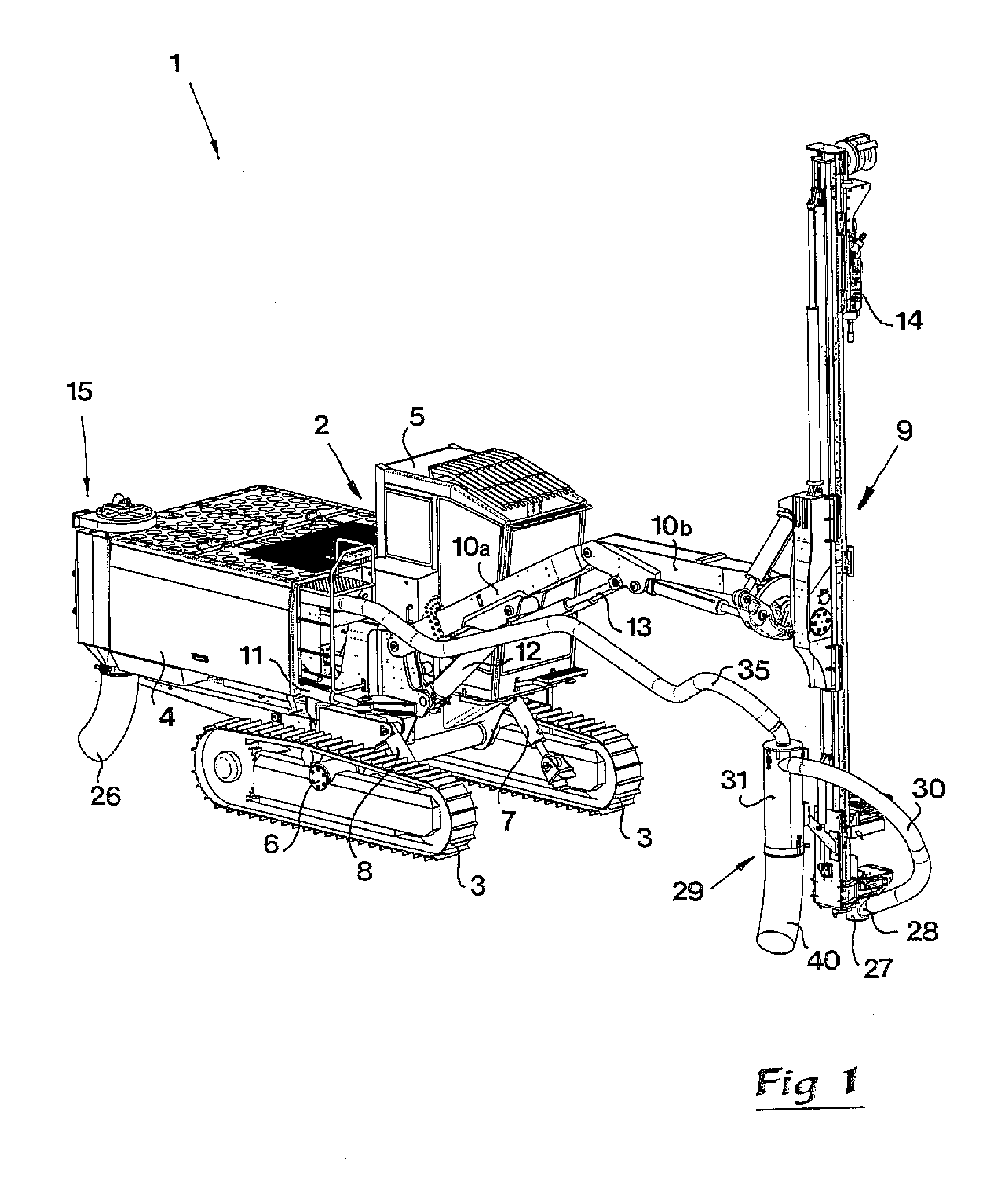
[0017]It shall be pointed out that the invention is applicable on all kinds of vehicles, constructions and arrangements, having a particle separator for dust and particle separation / collection. Thereto the term particle separator, as used in the claims as well as in the detailed description, includes different types of devices arranged to separate dust and particles from a created air flow. Said devices may be called and includes dust separators, dust collecting equipment, vacuum cleaners, and the like. The invention will be described below arranged in a mobile drill rig. This is to be regarded only as an example of a preferred application, and not as a limitation.

[0018]In FIG. 1 is shown a perspective view of a drill rig, generally designated 1. Said drill rig 1 comprises a vehicle body 2 carried by a pair of caterpillars 3, ground engagement elements, wheels or the like. The vehicle body 2 comprises a chassis 4 forming an engine compartment, located in the rear part of the vehicle...


PUM

PropertyMeasurementUnit
air pressureaaaaaaaaaa
air flow speedaaaaaaaaaa
rotational speedaaaaaaaaaa

Abstract

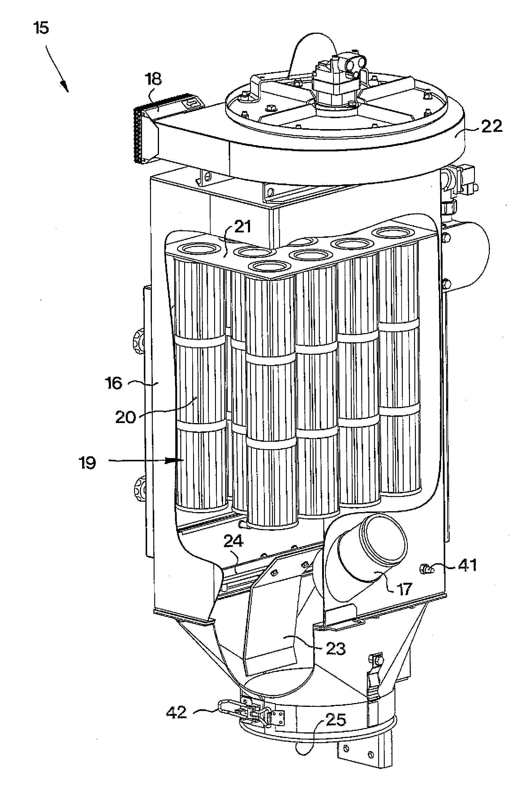
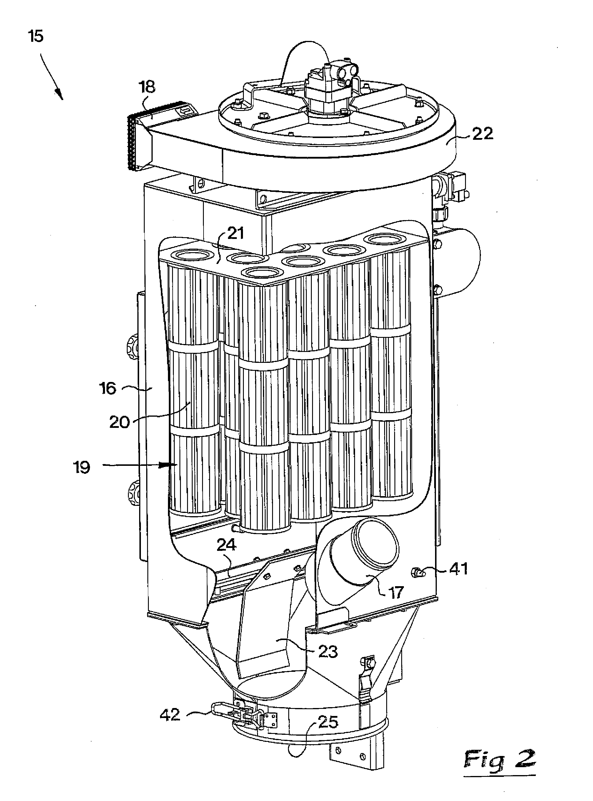
The invention relates to a particle separator for separating drill cuttings from an air flow, including a main separator (15) that comprises an air inlet (17) connectable to a suction nozzle, an air filter (19) arranged downstreams of said air inlet (17) and an air outlet (18) arranged downstreams of said air filter (19), the particle separator comprising means for generating an air flow, in the direction from said air inlet (17) to said air outlet (18). The particle separator also comprises means (41) for measuring a quantity of said air flow, and means for controlling the air flow generating means based on the measured quantity. The invention also relates to a drill rig comprising such a particle separator and a method for controlling such a particle separator.

Description

TECHNICAL FIELD OF THE INVENTION[0001]The present invention relates generally to the field of separation of particle from an air flow, and more specifically to a particle separator for separating drill cuttings from an air flow. The present invention also relates to a drill rig comprising such an particle separator, as well as a method for controlling such an particle separator.[0002]Said particle separator includes a particle separator for separating drill cuttings from an air flow, including a main separator that comprises an air inlet connectable to a suction nozzle, an air filter arranged downstreams of said air inlet and an air outlet arranged downstreams of said air filter, the particle separator comprising means for generating an air flow, in the direction from said air inlet to said air outlet.[0003]The invention is applicable to all kinds of constructions / vehicles equipped with a particle separator. However, a preferred application is for drill rigs, in particular mobile dr...

Claims


Application Information

Patent Timeline
Patent Type & Authority Applications(United States)
IPC IPC(8): B01D46/46B01D50/00
CPCB01D46/0068B01D46/2411B01D46/44E21B21/07E21B21/015E21B21/065B01D50/002B01D46/71B01D50/20B01D46/46E21B7/00
Inventor STENSTROM, JONAS
Owner ATLAS COPCO ROCK DRILLS
Learn More