Pressure sensor and method for manufacturing the same

a technology of pressure sensor and manufacturing method, which is applied in the field of pressure sensor, can solve the problems of degrading the degrading the temperature characteristics of the pressure sensor, and the inability of the pressure sensor using oil b>110/b> according to related art to measure the pressure of pure fluid that disfavors foreign substances, etc., and achieves improved q-factor of pressure sensing elements, improved temperature characteristics of the pressure sensor, and high thermal expansion

Inactive Publication Date: 2009-10-01
SEIKO EPSON CORP
View PDF14 Cites 7 Cited by
  • Summary
  • Abstract
  • Description
  • Claims
  • Application Information

AI Technical Summary

Benefits of technology

[0018]An advantage of the invention resolves at least part of the aforementioned problems, and is realized in accordance with the following aspects of the invention.
[0019]According to a first aspect of the invention, a pressure sensor includes: a first diaphragm that receives a pressure of an environment subjected to pressure measuring; a shaft which is coupled approximately perpendicular to a main surface of the first diaphragm so as to transmit the pressure; a swing arm which is joined to the shaft and is held to a retainer at a pivoting point as a fulcrum; and a pressure sensing element having a first end coupled to the retainer and a second end coupled to the swing arm, so that the pressure sensing element and the first diaphragm have the same displacement direction; and a housing that houses the shaft, the swing arm, and the pressure sensing element, as well as the retainer joined to an internal surface of the housing, so as to be sealed while exposing the first diaphragm to an external surface.
[0020]Here, the first diaphragm functions as a pressure receiving media that receives pressure from the environment subjected to pressure measuring. This eliminates the need to use oil as the pressure receiving media in the pressure sensor. Therefore, no oil leaks into the environment subjected to pressure measuring, allowing the pressure sensor to be used for measuring pressure in an environment such as a pure fluid that disfavors foreign substance.
[0021]Moreover, temperature characteristics of the pressure ...

Problems solved by technology

Therefore, a temperature change causes thermal distortion of the components constituting the pressure sensor.
Such thermal distortion works on the double-ended tuning fork resonator 109 as an unwanted stress, resulting in measured pressure value errors, thereby degrading the characteristics of the pressure sensor.
Therefore, the pressure sensor using the oil 110 according to related art cannot be used for measuring the pressure of pure fluid that disfavors foreign substance.
In the technique described in JP-A-2003-42896, a semiconductor is formed on a surface of the diaphragm, and therefore the cost of the diaphragm significantly increases.
Consequently, there is a drawback of not being able to improve the measurement precision.
Since a pressure sensor is used at a high temper...

Method used


Image

  • Pressure sensor and method for manufacturing the same
  • Pressure sensor and method for manufacturing the same
  • Pressure sensor and method for manufacturing the same

Examples


first embodiment

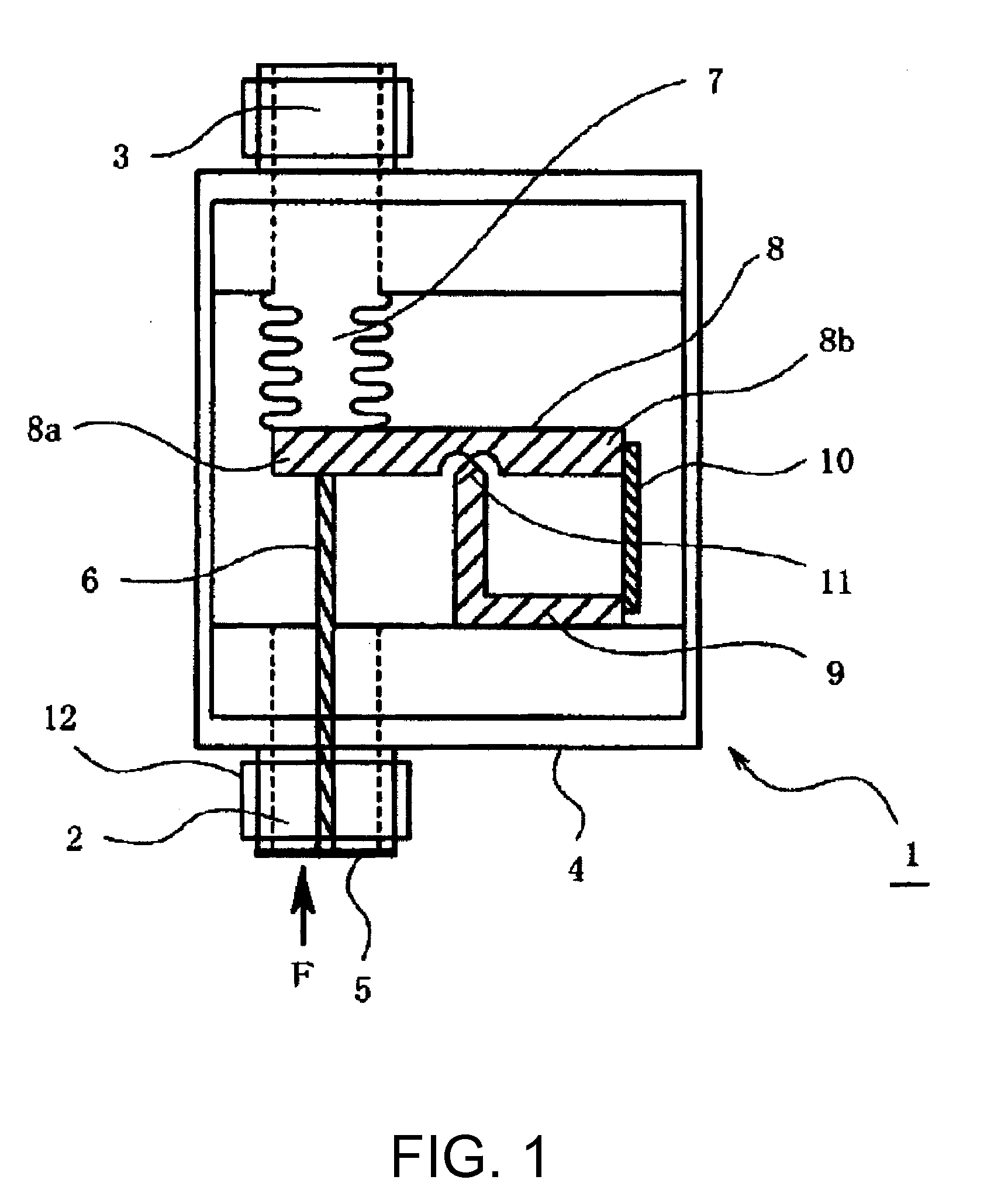
[0055]FIG. 1 is a schematic cross-sectional view illustrating a structure of a pressure sensor according to the invention.

[0056]A pressure sensor 1 shown in FIG. 1 includes a housing 4 which is a rectangular container with a vacuumed interior. Two pipe sleeves, serving as first and second attachments, are installed, protruding from the opposing end surface plates of the housing 4, and are coaxially arranged to face each other. The two pipe sleeves respectively include a first pressure input orifice 2 and a second pressure input orifice 3 which communicate to an interior of the housing 4. Components which will be described hereafter are housed inside the housing 4. A first (pressure receiving) diaphragm 5 is attached to an edge of the first pressure input orifice 2. The first diaphragm 5 is exposed outside the housing 4 and bends in accordance with a pressure of fluid subjected to measuring. A first shaft 6 (a first force transmitting member) is attached to the first diaphragm 5, wit...

second embodiment

[0076]a pressure sensor according to the invention will now be described.

[0077]FIG. 3 is a schematic view illustrating a structure of the second embodiment of the pressure sensor according to the invention. The same signs and numerals are used for the same parts as in FIG. 1, and their descriptions are omitted.

[0078]In the first embodiment, the bellows 7 is used as the pressure receiving means for the atmospheric pressure. Alternatively, in the second embodiment, a second diaphragm 22 and a second shaft 23 are used as the pressure receiving means for the atmospheric pressure. The second diaphragm 22 and the second shaft 23 are similar to the ones used as the pressure receiving means for the fluid subjected to measuring. As shown in FIG. 3, the second diaphragm 22 is formed so as to be exposed at an external surface of the housing which is at a opposite side from the first diaphragm 5, and one end of the second shaft 23 is joined to the center of a back side of the pressure receiving...

third embodiment

[0083]Subsequently, a pressure sensor according to the invention will now be described.

[0084]FIG. 4 is a schematic view illustrating a structure of a third embodiment of the pressure sensor according to the invention. The same signs and numerals are used for the same parts as in FIG. 1, and their descriptions are omitted. The pressure sensors according to the first and the second embodiments of the invention measure a gauge pressure (relative pressure), i.e. a pressure represented by having the atmospheric pressure as a reference of zero, and therefore the pressure receiving means for the atmospheric pressure is coupled to the end 8a of the swing arm 8. A pressure sensor according to the third embodiment measures an absolute pressure with respect to a vacuum state as a reference of zero. Therefore, only the pressure receiving means for the fluid subjected to measuring is coupled to the end 8a of the swing arm 8, and the pressure receiving means for the atmospheric pressure is remove...


PUM


Abstract

A pressure sensor includes: a housing; an attachment having a pressure input orifice communicating with an interior of the housing; a first diaphragm that seals an opening of the pressure input orifice of the attachment, an external surface of the first diaphragm being a pressure receiving surface; a force transmitting member having an end which is coupled approximately perpendicular to a main surface of the first diaphragm, the main surface being opposite from the pressure receiving surface; a swing arm which is joined to the force transmitting member and is held to a retainer at a pivoting point as a fulcrum; and a pressure sensing element having a first end coupled to the retainer and a second end coupled to the swing arm, so that a displacement direction of the force transmitting member is the same direction as a line joining the first end and the second end. In this pressure sensor, the force transmitting member, the swing arm, the pressure sensing element, and the retainer are housed inside the housing, and the retainer is fixed to an inner wall of the housing.

Description

BACKGROUND[0001]1. Technical Field[0002]The present invention relates to a pressure sensor and a method for manufacturing the same. This pressure sensor does not use oil as a pressure receiving media and therefore is suitable for broadening a scope of application of the pressure sensor.[0003]2. Related Art[0004]Pressure sensors that include piezoelectric resonating elements as pressure sensing elements are known as water pressure meters, barometers, and differential manometers. Piezoelectric resonating elements include, for instance, electrode patterns on planar piezoelectric substrates, having a detection axis in a direction in which a force is detected. When a pressure is applied in the direction of the detection axis, a resonant frequency of the piezoelectric resonating element changes and the pressure is detected using the fluctuation in the resonant frequency. Pressure sensors that use piezoelectric resonating elements as pressure sensing elements are disclosed in JP-A-56-11951...

Claims


Application Information

Patent Timeline
IPC IPC(8): G01L9/08H01L21/00
CPCG01L9/0033
Inventor MOTOYAMA, HISAO
Owner SEIKO EPSON CORP
Why Eureka
Try Eureka