
Multifocal intraocular lens

a multi-focal, intraocular lens technology, applied in the field of medicine, to achieve the effect of reducing eye trauma, increasing visual acuity, and shortening the post-surgical time period

Inactive Publication Date: 2009-09-24
ICON LAB
View PDF10 Cites 27 Cited by
  • Summary
  • Abstract
  • Description
  • Claims
  • Application Information

AI Technical Summary

Benefits of technology

[0005]The present invention accomplishes the objects to reduce eye traumatism during the surgery, to shorten post-surgical time period, to increase visual acuity, and to ensure a constant quality image at any distance from an object.
[0015]The statistical average for the human eye refraction is 20-22 D (diopters). The additional optical power of the diffractive part being from 8 to 12 D makes it possible to decrease the thickness of the lens significantly, e.g., by half or in a corresponding different magnitude depending on the additional optical power.
[0021]This kind of calculation can only be done with the help of known procedures of computer modelling of the entire optical system of the eye, which makes it possible to reduce or to minimize the spherical aberration of the optical system of the eye, including the cornea and all the refractive surfaces of the crystalline lens.
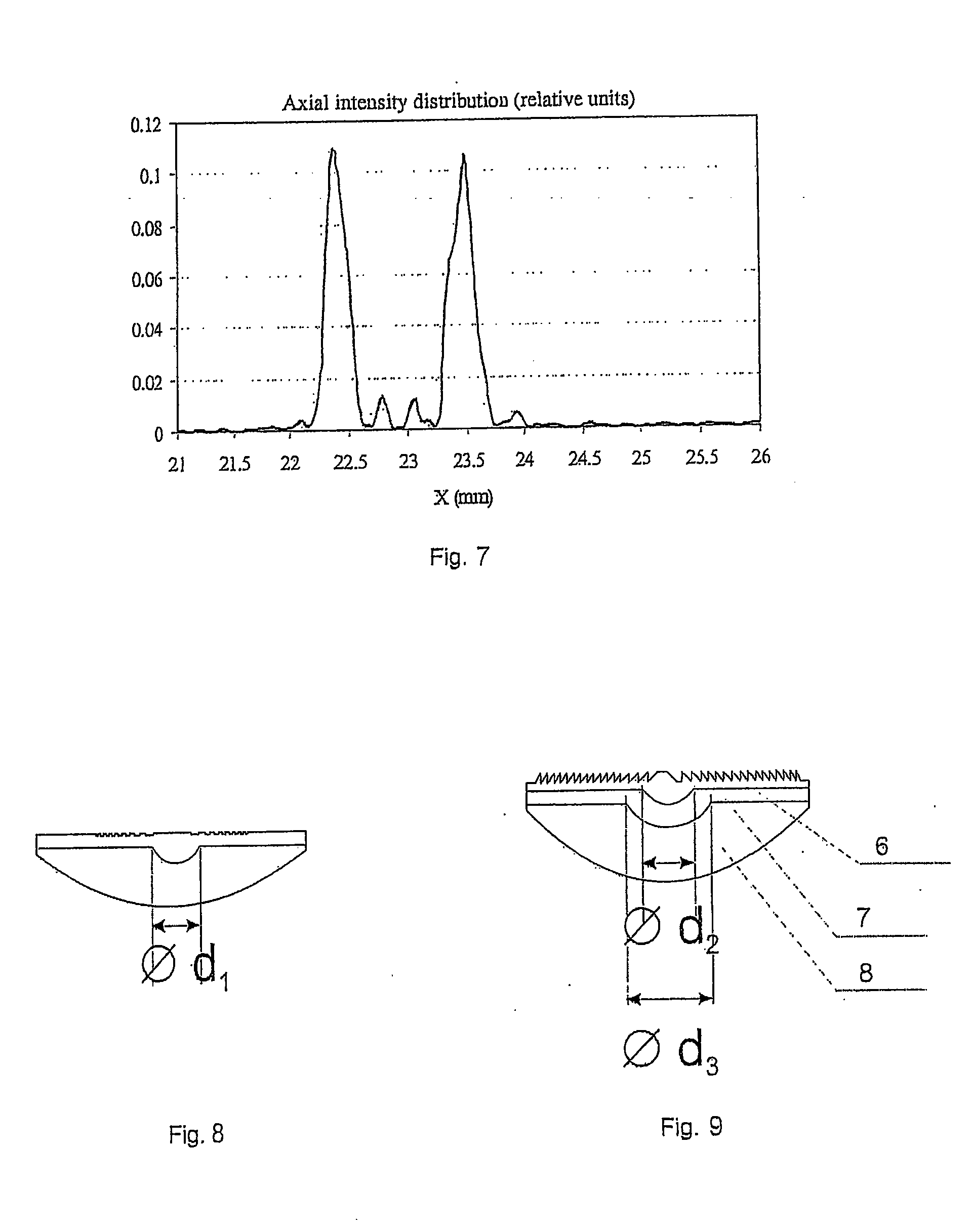
[0022]The IOL may contain either one additional refractive surface in its central part, which is represented by a spherical segment with the diameter d1 within the range of 1.6 to 2.6 mm, or 1.7 to 2.5 mm, preferably 1.8 to 2.4 mm or 2.0 to 2.2 mm, further changing radially outwardly into a plane. Such construction of the additional refractive surface avoids undesirable optical effects, such as a ‘halo’ with any intensity of the light on account of ‘superfluous’ light that appears on the boundary line of two zones with different refractive coefficients and goes beyond the circumference of the lens. Alternatively, two additional refractive surfaces may be provided, the first of which, counting from the external surface of the lens with the diffractive structure, is located in its central part and is represented by a spherical segment with the diameter d2 within the range of 1.4 to 1.8 mm, or 1.5 to 1.7 mm, further changing into a plane, and the second additional surface in its central part is represented by a spherical segment with the diameter d3 within the range of 2.1 to 2.6 mm or 2.2 to 2.5 mm or 2.3 to 2.4 mm into a plane.

Problems solved by technology

In fact, this creates a ban (a barrier) for utilizing this principle to create multifocal (pseudo-accomodating) IOLs designed for implantation through super small incisions.

Method used


Image

  • Multifocal intraocular lens
  • Multifocal intraocular lens
  • Multifocal intraocular lens

Examples


Embodiment Construction

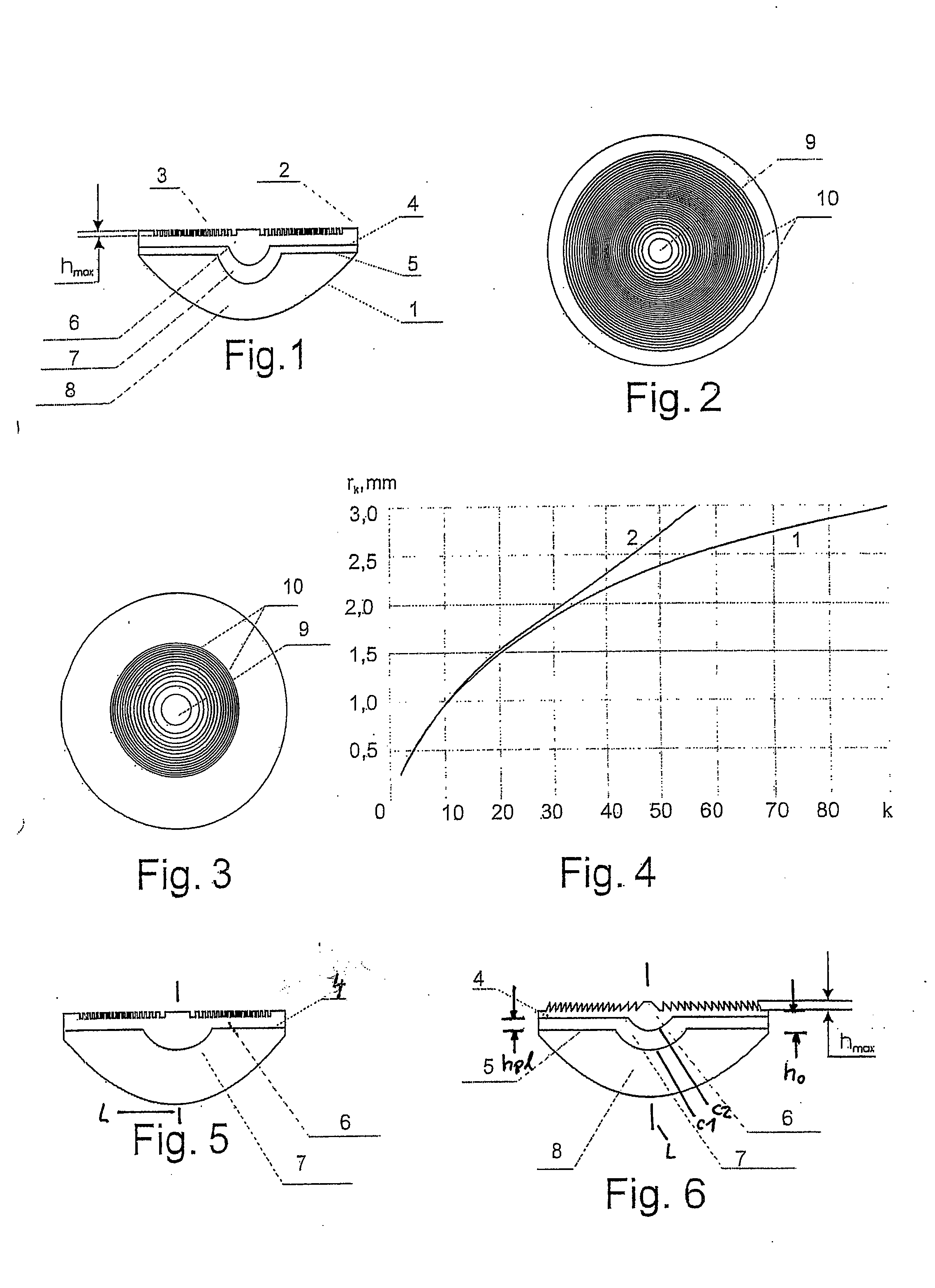
[0037]A proposed intraocular lens variant is depicted in FIG. 1. The lens has a plano-convex shape formed by two external refractive surfaces, one of which is represented by a sphere (1), and the other one is represented by a plane (2) with a diffractive structure microrelief in the form of rings superimposed all over its surface, the radii of these rings coinciding with the radii of the Fresnel zones (3). Inside the lens there is one (4) or two refractive surfaces (4, 5) represented by spheres. The external refractive surface, represented by a sphere, creates the main optical power by refraction phenomena. The additional optical power is provided by diffraction on the diffractive structure microrelief (3) and refraction on one or two internal surfaces (4, 5).

[0038]The microrelief is superimposed on the plane surface of the lens (2) in such a way that ring-type diffractive zones are formed on its surface (FIG. 2): the central zone (9) having the radius n and the ring-type concentric...


PUM


Abstract

A multifocal intraocular lens is provided having two external refractive surfaces and a longitudinal axis, and a diffractive structure superimposed on one of the surfaces in the form of a Fresnel zone. To reduce eye traumatism during surgery, to shorten post-surgical time period, to increase visual acuity, and to ensure a constant quality image at any distance from an object, a multifocal intraocular lens is proposed in which at least one additional refractive surface is inserted between the two external refractive surfaces, wherein the at least one additional refractive surface divides the lens volume into zones made of materials having different refraction coefficients.

Description

BACKGROUND OF THE INVENTION[0001]The present invention relates to medicine or, more specifically, to ophthalmology, and is intended for eyesight correction by implantation in an mammal eye, especially human eye.[0002]It is known that there exist hybrid type multifocal lenses, which have both a refractive and a diffractive part (See U.S. Pat. No. 4,637,697 Multifocal Contact Lenses Utilizing Diffraction and Refraction; International Patent Application Publication No. WO / 2004 / 113959 Bifocal Multiorder Diffractive Lenses For Vision Correction; U.S. Pat. No. 5,089,023 Diffractive / Refractive Lens Implant; U.S. Pat. No. 7,025,456 Diffractive Lenses For Vision Correction; Russian Patent RU 2,303,961 Multifocal Intraocular Lens; and U.S. Pat. No. 5,344,447 Diffractive Trifocal Intraocular Lens Design (prototype)).[0003]The drawback of this invention (as well as of all diffractive-refractive intraocular lenses (IOL), irrespective of their design features) lies in the fact that the thickness ...

Claims


Application Information

Patent Timeline
IPC IPC(8): A61F2/16
CPCA61F2250/0053A61F2/1618A61F2/1656
Inventor TREUSHNIKOV, VALERIYCHEREDNIK, VALENTINVIKTOROVA, ELENASTAROSTINA, OLGA
Owner ICON LAB
Learn More