
Methods for Purging Absorptive Materials Used in the Removal of Contaminates from an Aqueous Medium

a technology of absorption materials and aqueous medium, which is applied in the direction of water/sewage treatment by ion exchange, separation processes, ion exchangers, etc., can solve the problems of clogging the large volume housing units with suspended particulates in the aqueous medium, corresponding deterioration of water quality throughout the world, and contaminates naturally present. , to achieve the effect of limiting back pressure build-up and significant cost and time benefits

Active Publication Date: 2009-09-24
WRT INT
View PDF5 Cites 8 Cited by
  • Summary
  • Abstract
  • Description
  • Claims
  • Application Information

AI Technical Summary

Benefits of technology

[0013]The present invention provides methods, systems and apparatus for contacting an adsorption material with a continuous flow of aqueous medium for the removal of target contaminates from the aqueous medium. Adsorption material is constrained within a housing, typically a compartmentalized column, and aqueous medium is passed through the housing in an up-flow direction. Aspects of the invention limit back-pressure build-up from within the housing by preferentially eliminating particulates and other clogging materials from the adsorption material. Aspects of the invention provide a significant cost and time benefit over standard back-wash procedures used to dislodge particulates from within an adsorption material.
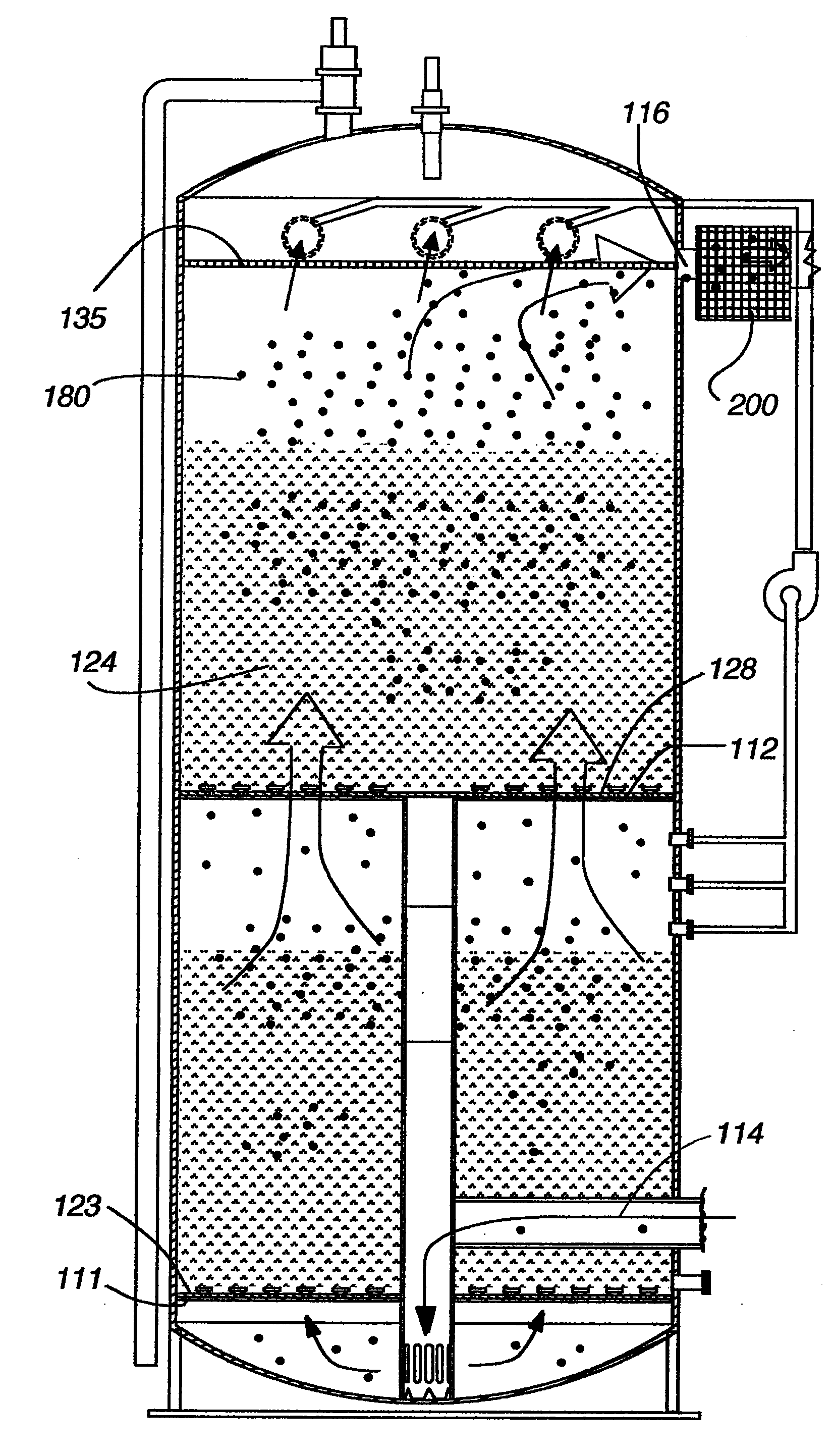
[0014]In one aspect of the invention, methods are provided for limiting back-pressure within a column by providing an environment within the column that preferentially causes particulates, located in most aqueous medium sources, trapped within the adsorption material to be moved toward, and ultimately out, of the column. The methods include stopping the normal up-flow direction of the aqueous medium through the column when a pre-determined level of back-pressure has built up within the column, thereby allowing the adsorption material and particulates to settle in the column. Stopping the up-flow of the aqueous medium within the column allows the adsorption material to settle within the column, where particulates are typically of a lesser density than the adsorption material, thereby settling slower and preferentially moving toward the outlet end of the adsorption material. The flow of the aqueous medium is then reversed and circulated within the compartments of the column to agitate and preferentially further move particulates to the top side of the adsorption material. The reversal of the aqueous medium provides a loop of flow from the middle inside compartment of the column, to the outside of the column, to the top inside of the column and then back down to the middle inside of the column. This loop of flow causing the particulates to preferentially settle and concentrate on the outlet side of the adsorption material. An alternative slow start can also be used to expand the adsorption material in the up-flow direction, removing particulates and allowing particulates within the top region of the adsorption material to also be removed from the column. Note that aspects of the present invention provide a method that preferentially moves particulates from the inlet of the column to the outlet of the column without major concentrations of particulates being trapped in the adsorption material.

Problems solved by technology

Increased industrial use of fresh water resources has resulted in a corresponding deterioration of water quality throughout the world, due partly to industrial related release of contaminates into the water.
In addition, contaminates are also naturally present in various fresh water resources, for example, high uranium content in fresh water resources throughout areas of Colorado, New Mexico and Texas.
One problem facing the water treatment industry is the clogging of these large volume housing units with suspended particulates in the aqueous medium.
Clogged adsorption material leads to increased pressures required to “force” the water through the adsorption and particulate material.
The clogging ultimately results in more costly water treatment and shut down to either replace the adsorption material or to perform costly backwash, where the aqueous medium and clogging particles are forced through and out of the column in the opposite direction of normal flow, carrying the particulates out of the column for disposal.
In particularly problematic cases, the particulates have a low level of radioactivity, for example, the particulates may have a low amount of uranium.

Method used


Image

  • Methods for Purging Absorptive Materials Used in the Removal of Contaminates from an Aqueous Medium
  • Methods for Purging Absorptive Materials Used in the Removal of Contaminates from an Aqueous Medium
  • Methods for Purging Absorptive Materials Used in the Removal of Contaminates from an Aqueous Medium

Examples


examples

Purging Column Limits Particulate Build-Up In Uranium Removal System

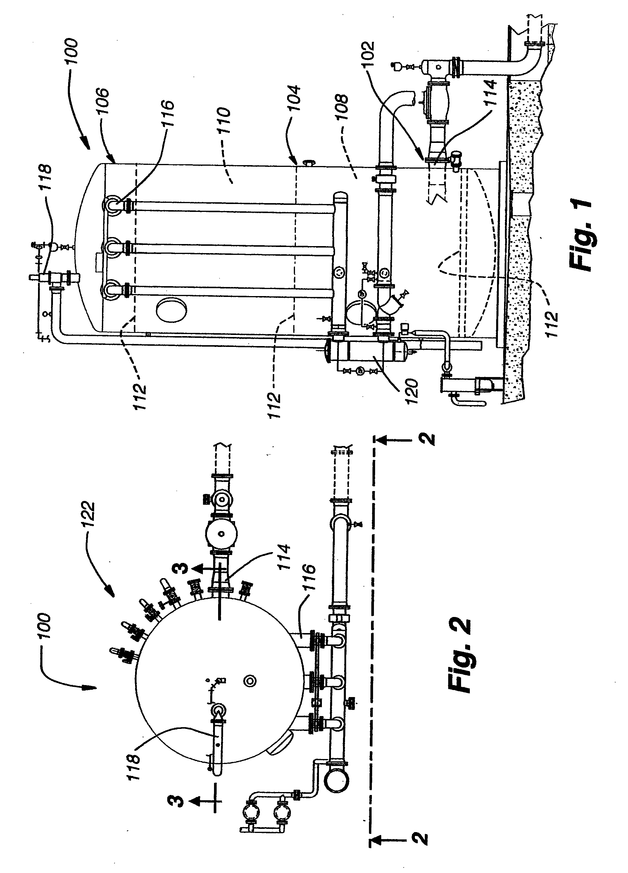
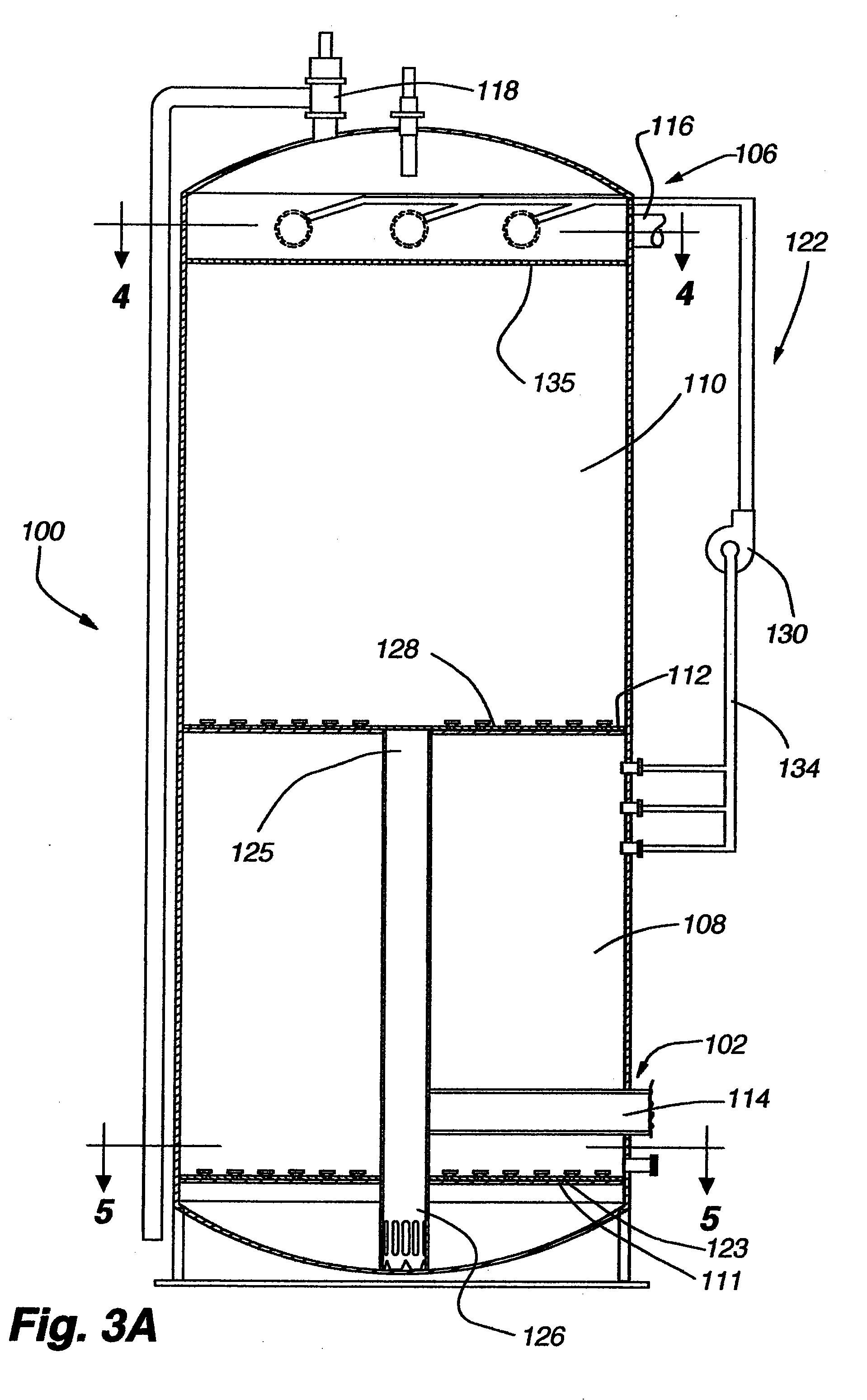
[0083]A uranium removal system was prepared for treatment of an aqueous medium source located in Dinwiddie, Va. The system was tested for the ability to treat and process a continuous flow of water for the removal of uranium. A pair of single stage, fluidized bed vessels rated for 150 pounds / in2 operating pressure were provided to the Dinwiddie drinking water supply. The vessels were designed to handle: 80 gallons per minute (gpm), having approximately 80 ppb uranium, and an empty bed contact time of 3.7 minutes at a hydraulic loading rate of 8.3 gallons per minute per square foot. The vessels were connected to each other in series and both had an up-flow design, see FIGS. 1-8.

[0084]In general, the systems of the present Example include Schedule 10 304L stainless steel piping designed to permit feed, discharge and bypass piping connections into the distribution system. The pipe was flanged and welded as required for...


PUM


Abstract

Methods, systems and apparatus are provided for purging an adsorptive material of entrapped particulates. Methods, systems and apparatus rely upon a reverse loop for reversing the flow of medium within an adsorption material, allowing particulates caught within the adsorption material to be preferentially moved through and out of the adsorption material.

Description

CROSS-REFERENCE TO RELATED APPLICATIONS[0001]This application is a divisional of U.S. patent application Ser. No. 11 / 560,205, entitled “SYSTEMS AND APPARATUS FOR PURGING ABSORPTIVE MATERIALS USED IN THE REMOVAL OF CONTAMINATES FROM AN AQUEOUS MEDIUM”, filed on Nov. 15, 2006, which application claims benefit under 35 U.S.C. §119(e) to U.S. Patent Application No. 60 / 737,159, filed Nov. 15, 2005, both of which are incorporated herein by reference in their entirety.[0002]The present disclosure is related to U.S. Patent Application No. 60 / 515,921 filed Oct. 29, 2003 and entitled DYNAMIC UP-FLOW ZEOLITE SYSTEM, which is herein incorporated by reference in its entirety.BACKGROUND OF THE INVENTION[0003]A. Field of the Invention[0004]The invention generally relates to methods, systems and apparatus for removal of a contaminate from an aqueous medium. More specifically, the invention provides methods, systems and apparatus for minimizing back-pressure in an adsorption material constrained wit...

Claims


Application Information

Patent Timeline
Patent Type & Authority Applications(United States)
IPC IPC(8): B01J49/00
CPCB01J49/0078C02F1/283C02F1/42C02F2303/16C02F2209/005C02F2209/03C02F2209/40C02F2001/422B01J49/60
Inventor WILLIAMS, CHARLES S.HEFFNER, SCOTT E.
Owner WRT INT
Learn More