
Continuous strip of thermal wristband/label forms

a technology of wristbands and labels, applied in the field of wristbands/labels, can solve the problems of not fully meeting the needs of owners of smaller thermal printers, limiting the ability of varying size forms to be processed, and approximately four inches in width, so as to reduce the need for replacing wristbands and reduce the cost of more complex forms. the effect of reliability

Active Publication Date: 2014-12-09
ZEBRA TECH CORP
View PDF197 Cites 29 Cited by
  • Summary
  • Abstract
  • Description
  • Claims
  • Application Information

AI Technical Summary

Benefits of technology

The patent text describes a need for a wristband / label combination that can be used with existing thermal printers and is low cost and simple in design. The wristband is non-laminating and can be torn off to suit different needs. The label area has various embodiments, including a two ply design with die cuts or weakness points, and a two ply design with Vee shaped nicks for easy tearing. This combination can be used in both new and existing installations, and helps reduce waste and lower costs.

Problems solved by technology

Some of these inventive designs have also been adapted for use with thermal printers, with their more limited capability to process forms of varying sizes.
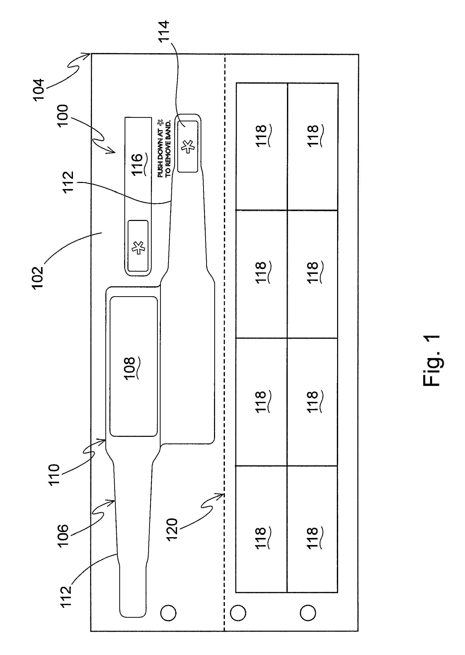
While this combination wristband / label design, as adapted for use with a thermal printer, has met with great commercial success, it's approximately four inch width has limited its usability to only those thermal printers having a “throat” large enough to accept it.
While many of the newer thermal printer designs are capable of accepting and printing a form as large as the aforementioned design, there is a substantial installed base of older thermal printers which have a two inch throat and which are thus unable to accept and use this combination wristband / label form.
Thus, while the inventors previous design has partially met this long, unsolved need, and has been received with great commercial success, it has not completely met the needs of the owners of smaller thermal printers.
Yet another factor to be considered with regard to the existing installed base is the matter of wristband expense.
As cost is an issue for these users, there would be resistance to adopting the form described and shown in FIG. 1 even if it could be made in a two inch format for the reason that its construction is more complex than a simple non-laminating wristband and, hence, more expensive.

Method used


Image

  • Continuous strip of thermal wristband/label forms
  • Continuous strip of thermal wristband/label forms
  • Continuous strip of thermal wristband/label forms

Examples


Embodiment Construction

[0011]The four inch, combo thermal form with self laminating wristband has been described above, and is a good and valuable invention subject to patent protection with several patents issued and others pending, all of which have been assigned to the assignee hereof. This form has been met with great commercial success and represents a significant improvement over the prior art.

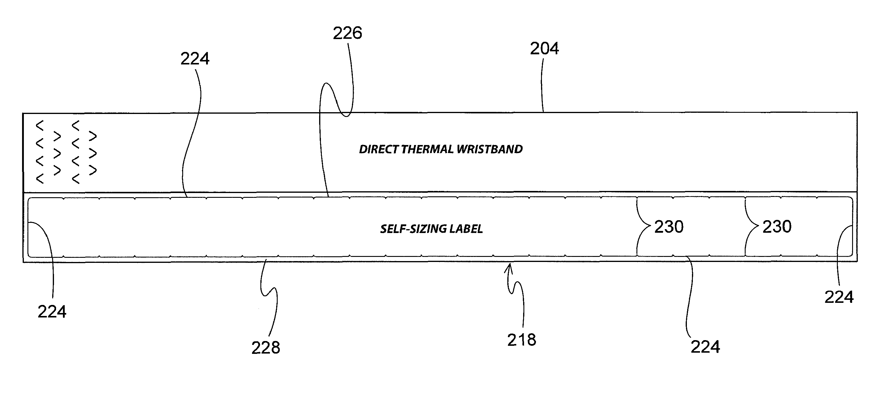
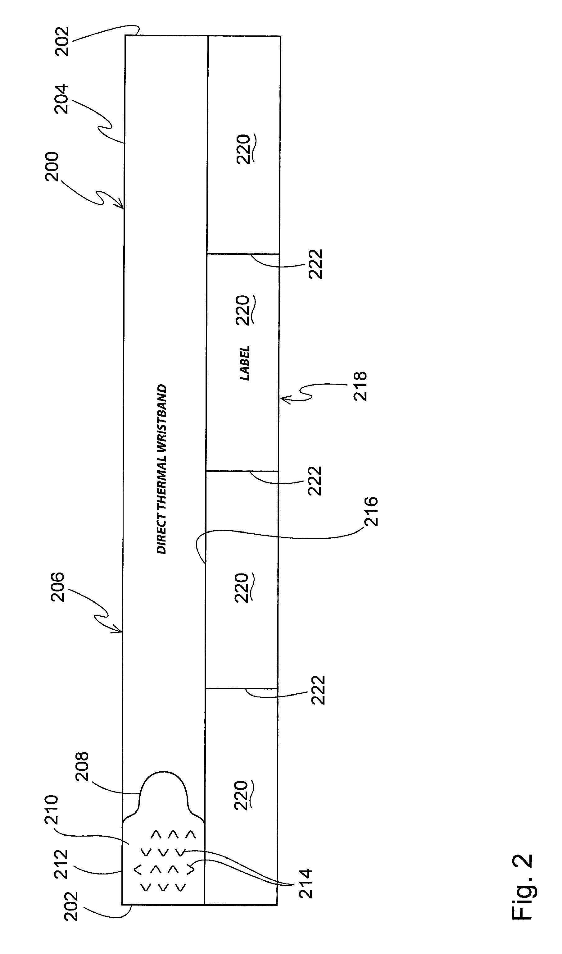
[0012]The present invention is exemplified by the preferred embodiments shown in the next several figures. FIG. 2 depicts a single two inch combo thermal form / assembly 200, but it is to be understood that preferably these form / assemblies are provided joined end to end at their narrower end, in a fan fold strip for ready feeding into the throat of a thermal printer. For clarity, a single form is shown but multiple forms would typically be joined with a line of weakness 202 separating adjacent forms. The line of weakness 202 could be a line of perforation, a die cut or other similar type of construction as would...


PUM


Abstract

A thermal printer processible combination wristband / label form has a top portion comprising a wristband which occupies substantially the entirety of thereof and a bottom portion comprising one of several alternative embodiments of labels. The label embodiments include a plurality of individually formed labels, a plurality of labels occupying substantially the entirety of the bottom portion, and a die cut defining a label portion with pairs of nicks spaced along an upper and lower border of the die cut and between which a user may tear off labels of a desired length including different lengths. The form is produced in quantity and joined together into a fan fold strip having an overall width of a nominal two inches so as to be capable of being printed by relatively older thermal printers having a nominal two inch throat.

Description

BACKGROUND AND SUMMARY OF THE INVENTION[0001]Combination wristband / label forms have become well known in the business form and medical arts, and commercialized to great success, through the innovative efforts of the inventor herein as well as others through the company which is the assignee hereof. Examples of the inventive wristband / label forms which have met with significant commercial success may be found in just a few representative US patents which have already been issued, and for which multiple patent applications remain in prosecution. See, for example, issued U.S. Pat. Nos. 7,017,293; 7,017,294; 7,047,682; 7,222,448; and 7,325,347.[0002]While many of these wristband / label designs are intended for printer processing through a laser printer, with its generally universal capability to process forms of widely varying dimensions, a couple of these inventive designs have been particularly identified for printing by thermal printers. Some of these inventive designs have also been ...

Claims


Application Information

Patent Timeline
Patent Type & Authority Patents(United States)
IPC IPC(8): G09F3/02G09F3/00
CPCG09F3/0288G09F2003/0227G09F2003/0267G09F2003/0222G09F2003/0201G09F3/005
Inventor GREER, MARK
Owner ZEBRA TECH CORP
Learn More