
Suction unit and heat exchange fin manufacturing machine

Inactive Publication Date: 2009-09-24
HIDAKA SEIKI KK
View PDF49 Cites 3 Cited by
  • Summary
  • Abstract
  • Description
  • Claims
  • Application Information

AI Technical Summary

Benefits of technology

[0013]An object of the present invention is to provide a suction unit, which is capable of solving the problems of the conventional suction unit (i.e., lower speed with respect to a processing speed of the press unit, durability issue, noise), matching an operation speed of the suction unit with processing speeds of the press unit, etc. and improving manufacturing efficiency of a heat exchange fin manufacturing machine.
[0017]Further, by using such a blocking plate, a processing speed of the suction unit could be accelerated, and the problems of durability issue and noise could be solved.
[0027]In the suction unit, the blocking plate may be capable of opening and closing the opening section. With this structure, sucking air from the opening section can be securely performed and stopped.
[0028]In the suction unit, a plurality of the blocking plates may be provided and synchronously moved. With this structure, sucking the elongated piece by the sucking section and releasing the heat exchange fin therefrom can be rapidly performed.
[0031]Therefore, the processing speed of the suction unit of the present invention can be higher than that of the conventional suction unit, in which the blocking plate is driven by the cylinder unit, so that processing speeds of the press unit, etc. can be accelerated.
[0032]Further, the blocking plate is moved without contacting the cylindrical member, so that durability of the blocking plate and the cylindrical member can be improved and the problem of noise can be prevented.

Problems solved by technology

The manufacturing efficiency of the heat exchange fin must be increased, but speeding up the conventional suction unit 108 is limited.
Further, by increasing the manufacturing efficiency of the heat exchange fin, number of making the blocking plate 118 contact with the cylindrical member 114 must be increased, so problems of durability issue and noise occur.

Method used


Image

  • Suction unit and heat exchange fin manufacturing machine
  • Suction unit and heat exchange fin manufacturing machine
  • Suction unit and heat exchange fin manufacturing machine

Examples


Embodiment Construction

[0041]Preferred embodiments of the present invention will now be described in detail with reference to the accompanying drawings.

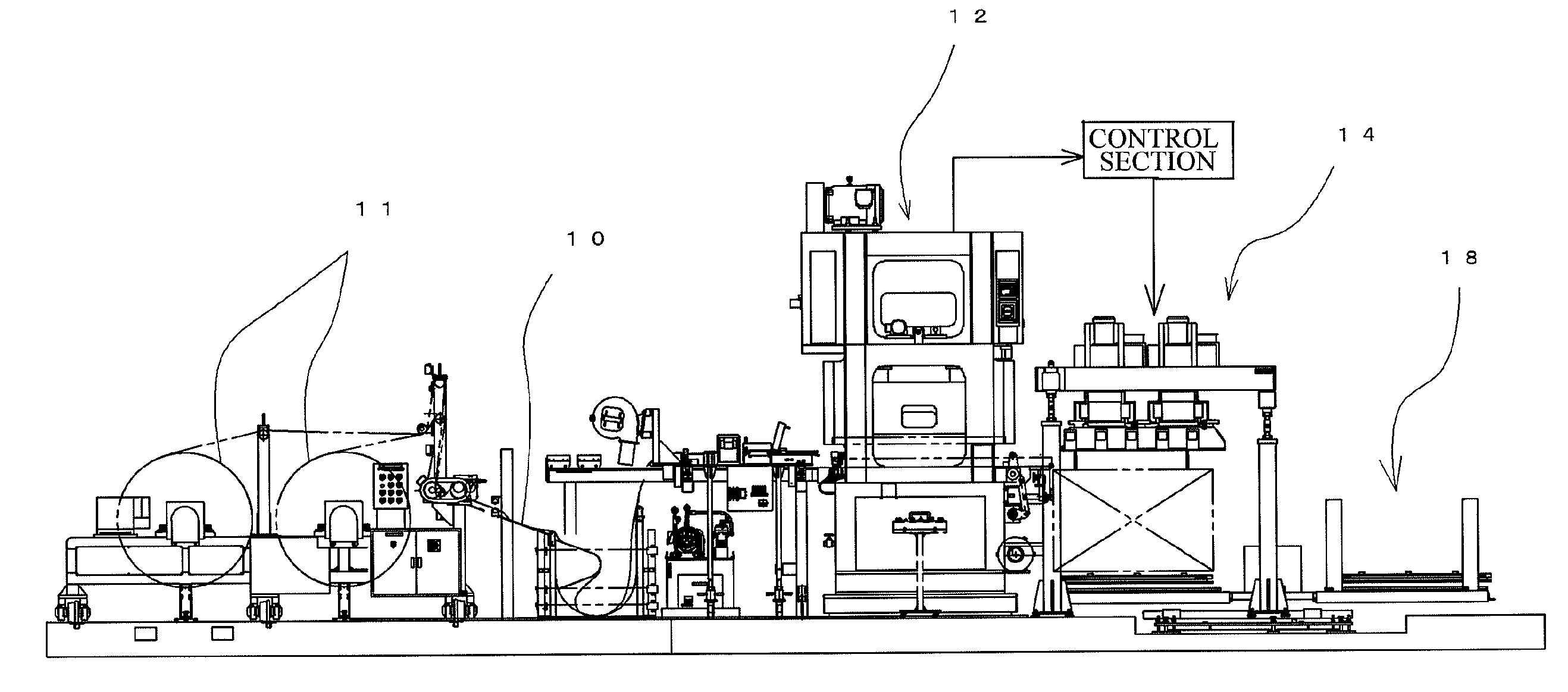
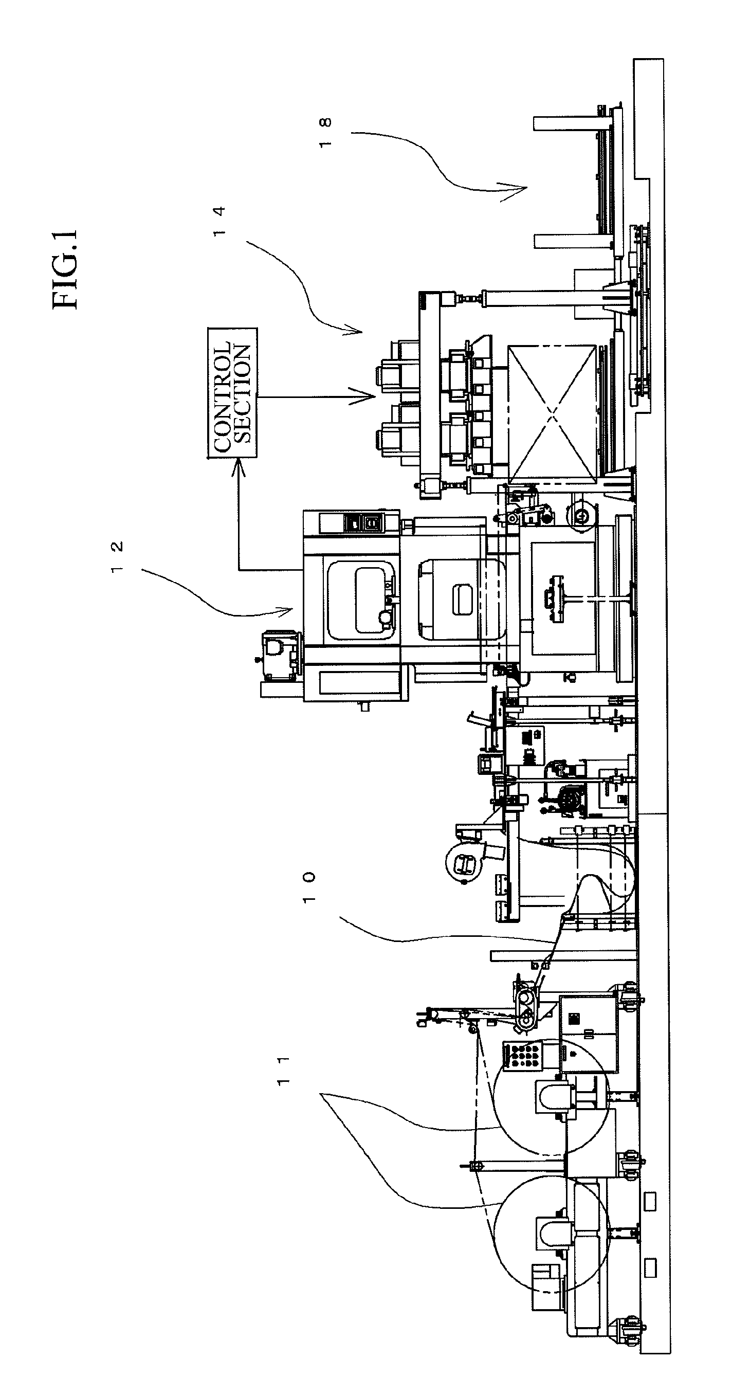
[0042]FIG. 1 shows an embodiment of a heat exchange fin manufacturing machine having a suction unit of the present invention. In the heat exchange fin manufacturing machine shown in FIG. 1, a band-shaped metal thin plate is wound as a coil 11, and the band-shaped metal thin plate 10 extended from the coil 11 is tensioned and fed to a press unit 12. In the press unit 12, a number of collared through-holes are formed in the fed metal thin plate 10 by dies, and then the metal thin plate 10 is cut by a cutter (not shown) of the press unit 12 and formed into a plurality of elongated pieces, each of which has a prescribed width. The elongated pieces are fed to a suction unit 14 in order. When the elongated piece is fed a prescribed length to the suction unit 14, the fed part of the elongated piece is cut by another cutter (not shown) of the press unit 12 so as t...


PUM


Abstract

The suction unit of the present invention comprises: a cylindrical member having a sucking section capable of sucking an elongated piece having faced the sucking section, an opening section being opened at a prescribed position at which the elongated piece is prohibited to face the opening section, and a suction unit for sucking air from the sucking section and the opening section; a blocking plate being moved without contacting the cylindrical member, the blocking plate prohibiting the air suction from the opening section when the elongated piece faces the sucking section, the blocking plate allowing the air suction from the opening section when the elongated piece sucked by the sucking section is cut and formed into the heat exchange fin; and a control section controlling the electric motor so as to place the blocking plate at a sucking position when the elongated piece faces the sucking section and at a releasing position when the elongated piece is cut and formed into the heat exchange fin.

Description

BACKGROUND OF THE INVENTION[0001]The present invention relates to a suction unit and a heat exchange fin manufacturing machine, more precisely relates to a suction unit, which is used in a heat exchange fin manufacturing machine cutting a band-shaped metal thin plate to form into heat exchange fins having a prescribed length, each of which has a plurality of collared through-holes, and which feeds the heat exchange fins to a stacking unit, and a heat exchange fin manufacturing machine equipped with the suction unit.[0002]A heat exchange fin of a heat exchanger, e.g., air conditioner, is a rectangular metal thin plate, in which a plurality of collared through-holes, into which heat exchange tubes will be inserted, are formed and arranged in the longitudinal direction. The heat exchange fin may be manufactured by, for example, a machine disclosed in Japanese Patent Gazette No. 2002-178065.[0003]An outline of the heat exchange fin manufacturing machine is shown in FIG. 5. In the machin...

Claims


Application Information

Patent Timeline
IPC IPC(8): B26D7/06B26D7/27
CPCB21D53/02B21D43/18Y10T83/207Y10T83/2033B21D43/20
Inventor ENDO, MASASHIIWASAKI, MAKOTO
Owner HIDAKA SEIKI KK
Learn More