Eureka AIR delivers breakthrough ideas for toughest innovation challenges, trusted by R&D personnel around the world.

System and apparatus for cascading and redistributing HDTV signals

Inactive Publication Date: 2009-09-17
TAIWAN SEMICON MFG CO LTD
View PDF9 Cites 70 Cited by
  • Summary
  • Abstract
  • Description
  • Claims
  • Application Information

AI Technical Summary

Benefits of technology

[0014]It is still another object of the invention to provide solutions for redistributing signals over a wireless connection within a service area, which require minimal changes to the existing equipment. For example, the architectures described herein enable redistribution of TV signals with minimal changes to the TV receiver.
[0018]Advantageously, the invention provides low equipment costs, achieves better performance, enhances spectrum utilization, and therefore provides a particularly effective wireless redistribution of signals, and in particular of TV signals.

Problems solved by technology

Such small areas include single-family residential, multi-dwelling units, small / home offices, small businesses, multi-tenant buildings, and public and private campuses, all characterized by a restricted space, with numerous obstacles such as walls, furniture, metallic appliances, etc.
Current hardwire solutions require cabling hardware, with concomitant logistical overhead and aesthetic issues.
Wireless methods are known, but such methods typically require significant compression prior to local distribution, and an a-priori reservation of wide, interference-free bandwidth.
Frequently though, locations are without, or are not suitable for, high bandwidth hardwired systems.
Further, aesthetic matters pertaining to cables may render such connections undesirable.
While this solution reduces the cabling necessary for connecting the devices, it has important disadvantages.
Some solutions proposed to address this issue involve the use of beam-forming technology, but this increases the costs and reduces the space available for the overall system hardware.
One is that governmental and other imposed allocation of spectra may limit such conventional retransmission.
Another is that a conventional repeater typically amplifies and repeats not only the information signal of interest but also various noise and interference signals.
However, conventional Wi-Fi may not provide a sufficient continuous data rate to satisfactorily support the HDTV picture quality.
Further, link quality in Wi-Fi is often compromised due to various and often uncontrollable interference.

Method used

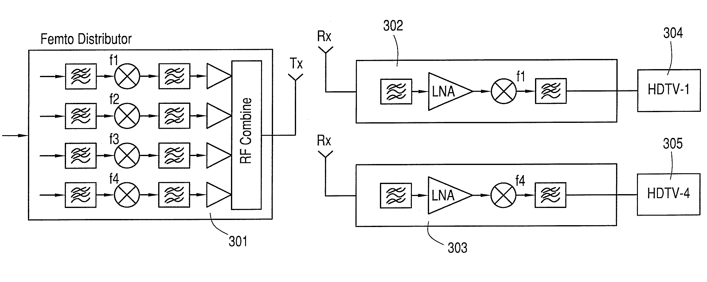
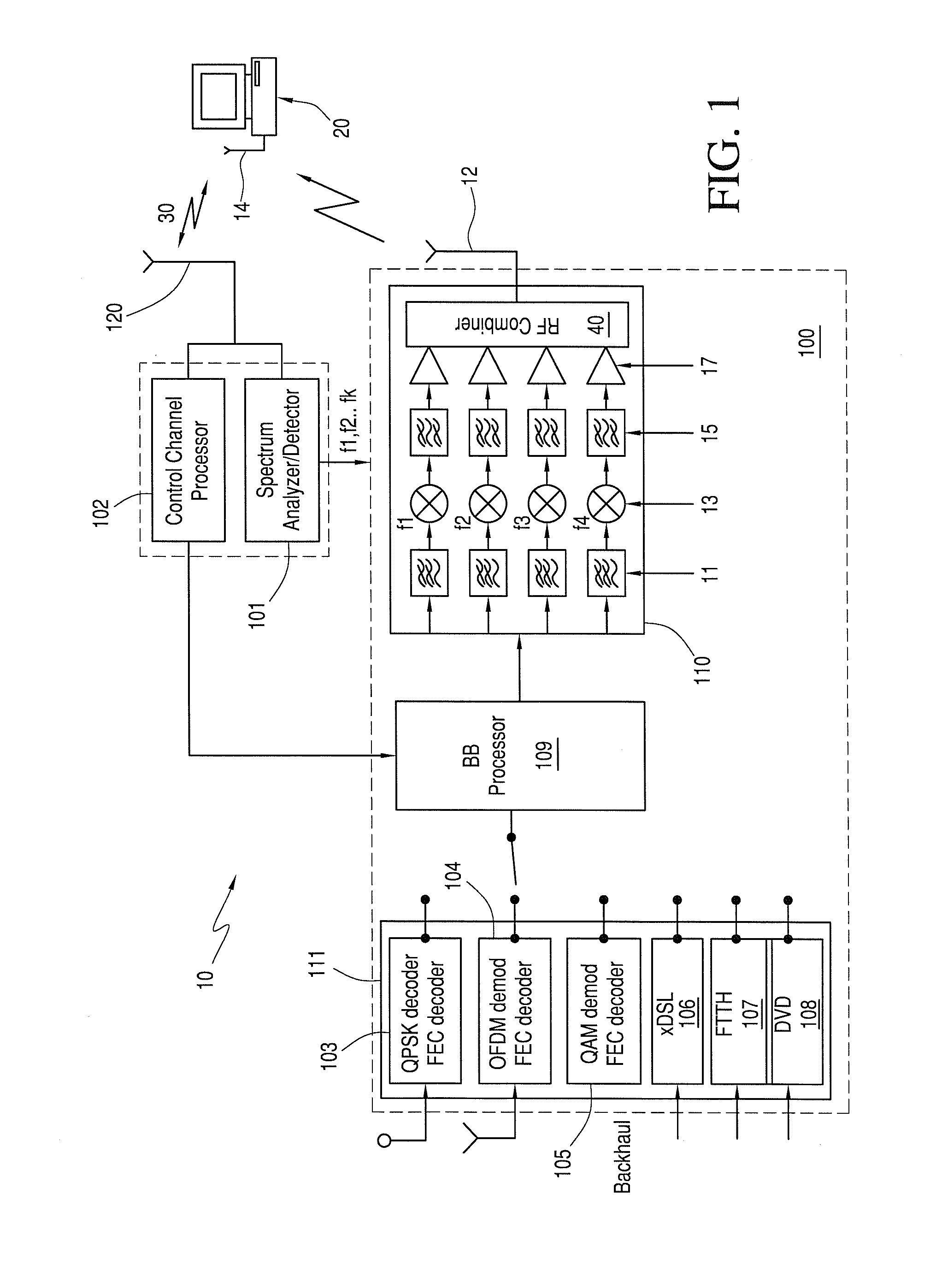
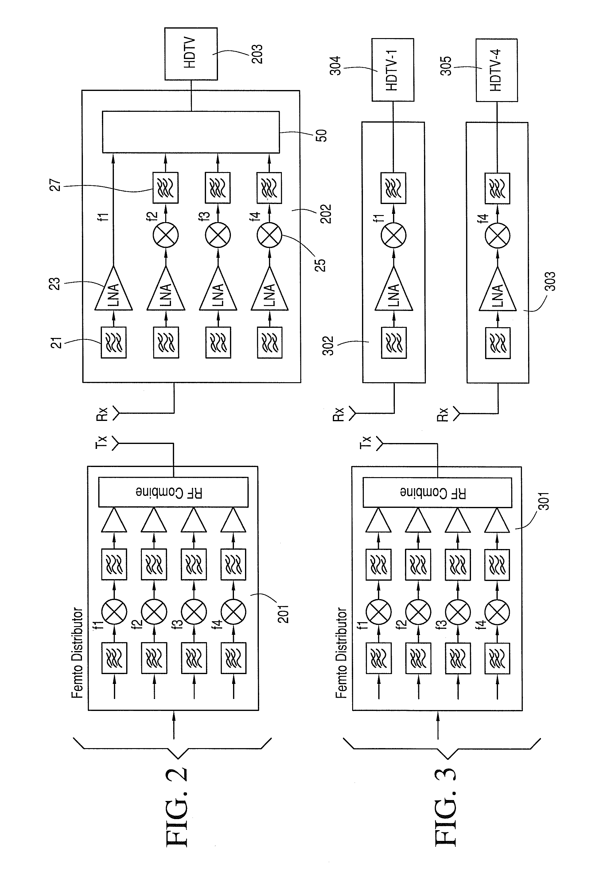

Image

  • System and apparatus for cascading and redistributing HDTV signals
  • System and apparatus for cascading and redistributing HDTV signals
  • System and apparatus for cascading and redistributing HDTV signals

Examples


Embodiment Construction

[0029]It is known that various regulatory bodies around the word allocate the spectrum for specific uses and, in most cases, license the rights to parts of the spectrum. These frequency allocation plans, in many cases, mandate that specified parts of spectrum remain free (unused) between allocated bands for technical reasons (e.g. to avoid interference). As well, these regulatory bodies provide for unused spectrum which has either never been licensed, or is becoming free as a result of technical changes. Efficient use of this valuable resource is the current research trend snugly tied to the evolution of modern data communication systems.

[0030]There is a global trend to transition from the analog to digital TV (DTV), driven by the higher quality of the digital signals resulting in a better viewer experience, ability of providing personalized and interactive services, and a more efficient use of the spectrum.

[0031]For example, in North America, the TV broadcasters currently use the V...


PUM


Abstract

Redistribution of multimedia signals or the like within a service area is performed by identifying one or more pieces of white space in the VHF / UHF spectrum, selecting a carrier frequency for each piece of white space spectrum, parsing the signal into a like number of components and modulating each component over a carrier frequency. The receiving device performs the reverse operation for reconstructing the signal.

Description

CLAIM OF PRIORITY[0001]This U.S. patent application claims priority to U.S. Provisional Patent Application No. 61 / 064,614 entitled “System and Apparatus for Cascading and Re-Distributing HDTV Signals” filed Mar. 17, 2008, which is hereby incorporated by reference.BACKGROUND[0002]1. Field of the Invention[0003]This invention relates generally to the local distribution of high bandwidth information signals.[0004]2. Description of Related Art[0005]There is a recognized demand to provide an inexpensive and efficient way to broadcast multimedia content within a specified small area using wireless solutions. Such small areas include single-family residential, multi-dwelling units, small / home offices, small businesses, multi-tenant buildings, and public and private campuses, all characterized by a restricted space, with numerous obstacles such as walls, furniture, metallic appliances, etc. There is a trend to provide the subscribers in this market with architectures that are comfortable, e...

Claims


Application Information

Patent Timeline
IPC IPC(8): H04N7/18
CPCH04H20/02H04H20/42H04H20/33
Inventor WU, SHIQUANCOLLINGS, TIMOTHY D.YEE, JUNG
Owner TAIWAN SEMICON MFG CO LTD
Why Eureka
Eureka Blog
Learn More