
Control device of internal combustion engine

Inactive Publication Date: 2009-09-17
HONDA MOTOR CO LTD
View PDF5 Cites 22 Cited by
  • Summary
  • Abstract
  • Description
  • Claims
  • Application Information

AI Technical Summary

Benefits of technology

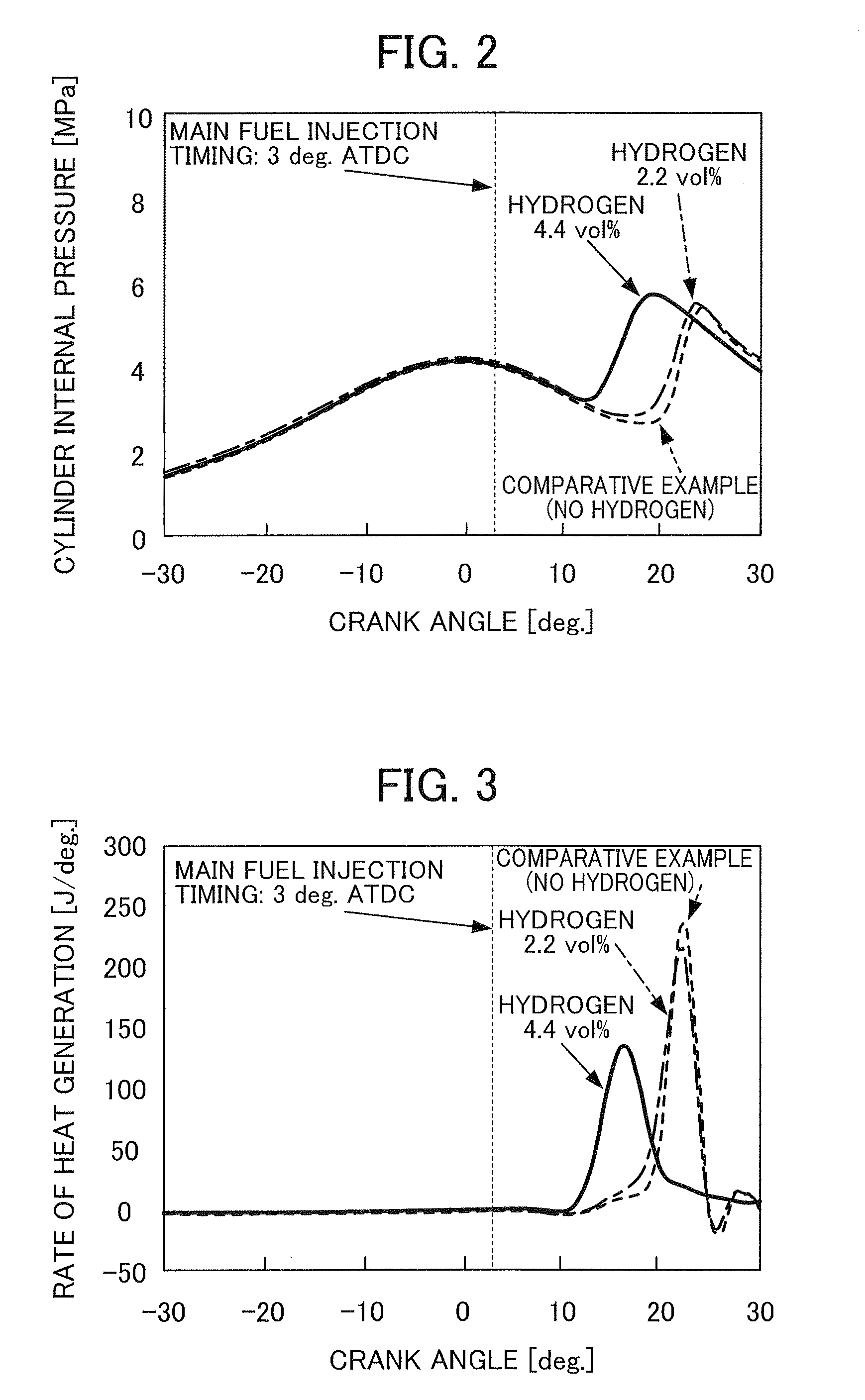
[0017]Accordingly, even in a case where the supply timing of the main fuel is retarded from the standard injection timing of the engine, for example, the combustion is made gradual with shortening ignition retarding, in addition to reducing noise and vibration. Therefore, as described above, combustion in moderate and high load regions can be improved, and the operating region can be expanded. In addition, it is possible to also reduce the emission amounts of CO and unburnt HC. In this way, exhaust emissions and the main fuel consumption can be further improved.
[0021]According to this configuration, by way of injecting the main fuel and gas containing hydrogen by the fuel injector and the gas injector inject, the supply timing and the supply period of these main fuel and gas can be controlled accurately. In particular, in order to establish stable combustion in the premixed charge compression ignition internal combustion engine, it is necessary to control the supply timing and the supply period of the main fuel and gas accurately.

Problems solved by technology

However, in the above-mentioned premixed charge compression ignition internal combustion engine, there has been a problem in that noise and vibration increase due to instantaneous combustion in moderate and high load regions.
However, in the technique for retarding fuel injection timing, it has been known that the fuel efficiency and the stability of ignition and combustion deteriorates substantially.
In the premixed charge compression ignition internal combustion engine, the combustion system is limited only to a low load operation region under present circumstances due to the above-mentioned problem in moderate and high operating regions.

Method used


Image

  • Control device of internal combustion engine
  • Control device of internal combustion engine
  • Control device of internal combustion engine

Examples


Embodiment Construction

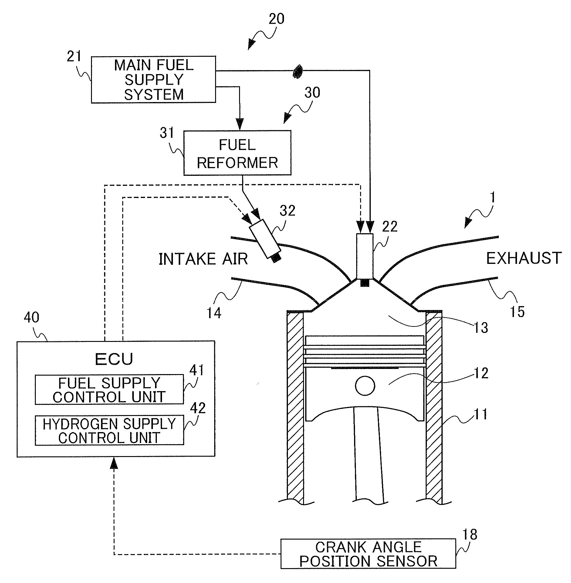
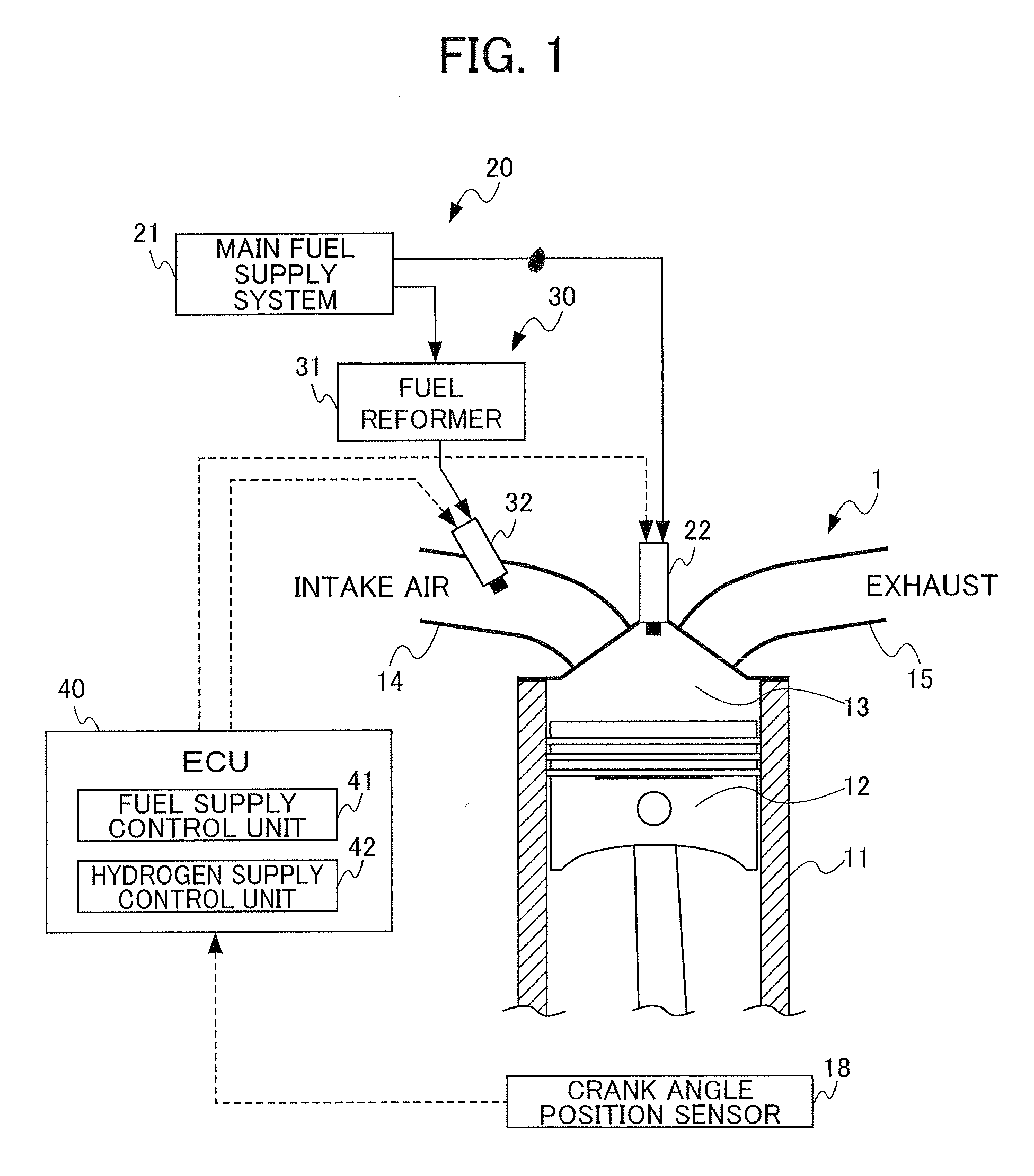
[0035]FIG. 1 is a diagram illustrating the structure of the internal combustion engine and the control device thereof according to one embodiment of the present invention. The internal combustion engine 1 (hereinafter referred to as “engine”) is a premixed charge compression ignition (hereinafter referred to as “PCCI”) internal combustion engine that causes compression ignition within the combustion chamber 13, which is formed in the cylinder 11, by a piston 12. It should be noted that FIG. 1 shows only one of a plurality of cylinders in the engine 1. This engine 1 is provided with a fuel supply means 20 that supplies the main fuel and a hydrogen supply means 30 that supplies gas containing hydrogen.

[0036]The fuel supply means 20 is configured to include a main fuel supply system 21 that supplies the main fuel and a fuel injector 22 that supplies the main fuel supplied from the main fuel supply system 21.

[0037]The main fuel supply system 21 is provided with a fuel tank that stores t...


PUM


Abstract

A control device for a premixed charge compression ignition (PCCI) internal combustion engine is provided, capable of stable operation over a wide operating range. The control device of an engine 1 comprises: a fuel supply means 20 of supplying the main fuel to the engine 1; an hydrogen supply means 30 of supplying reformed gas containing hydrogen; a fuel supply control unit 41 of controlling an injection timing and an injection period of the main fuel supplied from the injector 22 of the fuel supply means 20 based on the PCCI combustion condition of the engine 1; and a hydrogen supply control unit 42 of controlling an injection timing and an injection period of reformed gas from the gas injector 32 of the hydrogen supply means 30 based on the PCCI combustion condition.

Description

[0001]This application is based on and claims the benefit of priority from Japanese Patent Application No. 2008-062615, filed on 12 Mar. 2008, the content of which is incorporated herein by reference.BACKGROUND OF THE INVENTION[0002]1. Field of the Invention[0003]The present invention relates to a control device of an internal combustion engine, in particular, to a control device of a premixed charge compression ignition (PCCI) internal combustion engine capable of stable operation over a wide operating range.[0004]2. Related Art[0005]Conventionally, a diffusion combustion system used for a diesel engine compresses air drawn into a combustion chamber, and then injects fuel into this compressed air to cause self-ignition, thereby causing combustion. Such a diesel engine has thermal efficiency superior to that of a gasoline engine. However, since there locally exists an excessive fuel concentration region and a high temperature region due to non-uniformly atomized fuel distribution, t...

Claims


Application Information

Patent Timeline
IPC IPC(8): F02B43/08
CPCF02B1/12F02B43/10F02B2275/14F02B2275/16Y02T10/123F02D41/3035F02M25/12Y02T10/128F02D41/0025Y02T10/12
Inventor SHIMASAKI, YUICHIKABASHIMA, HAJIME
Owner HONDA MOTOR CO LTD
Learn More