
Thermal Cover

a technology of thermal cover and liquid transmission mechanism, which is applied in the direction of service pipe system, pipe heating/cooling, mechanical equipment, etc., can solve the problems of premature deterioration of system components, liquid transmission mechanism and system, piping system and associated devices, etc., and achieves the effect of reducing heat transfer and superior passive freeze resistan

Inactive Publication Date: 2009-09-10
BULLER DENNIS WILSON
View PDF5 Cites 6 Cited by
  • Summary
  • Abstract
  • Description
  • Claims
  • Application Information

AI Technical Summary

Benefits of technology

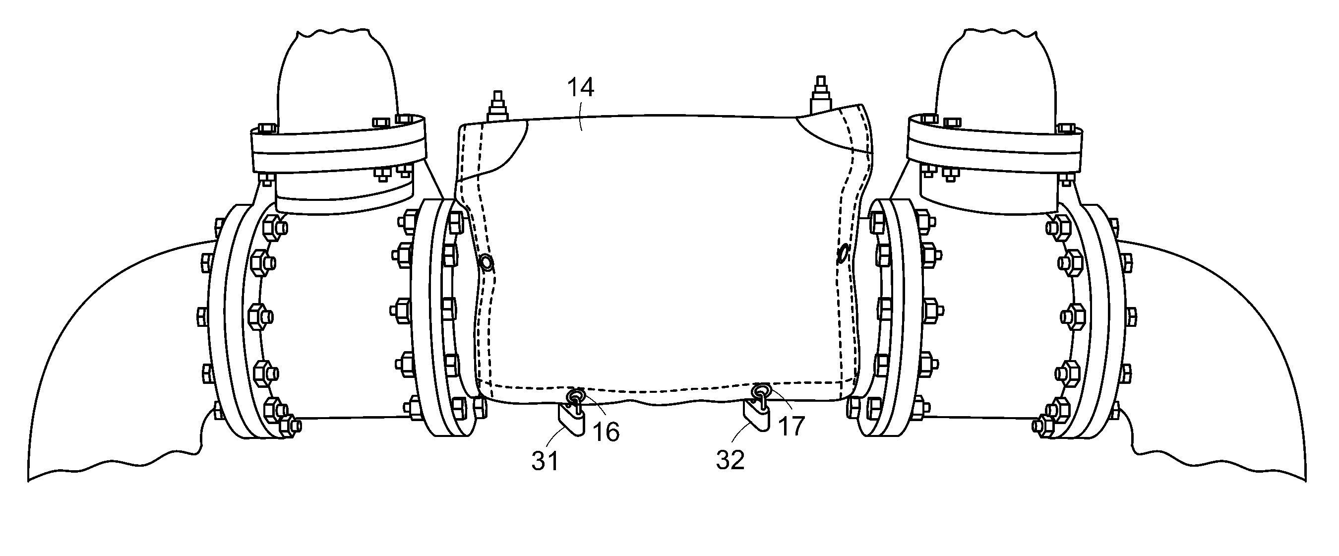
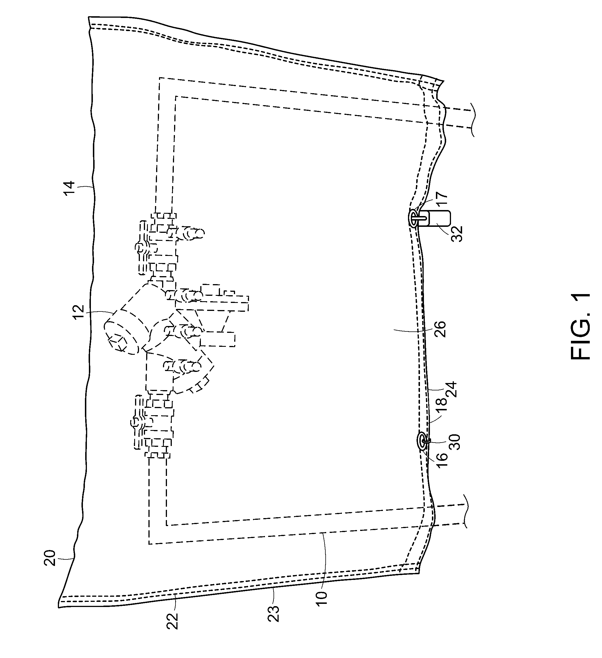
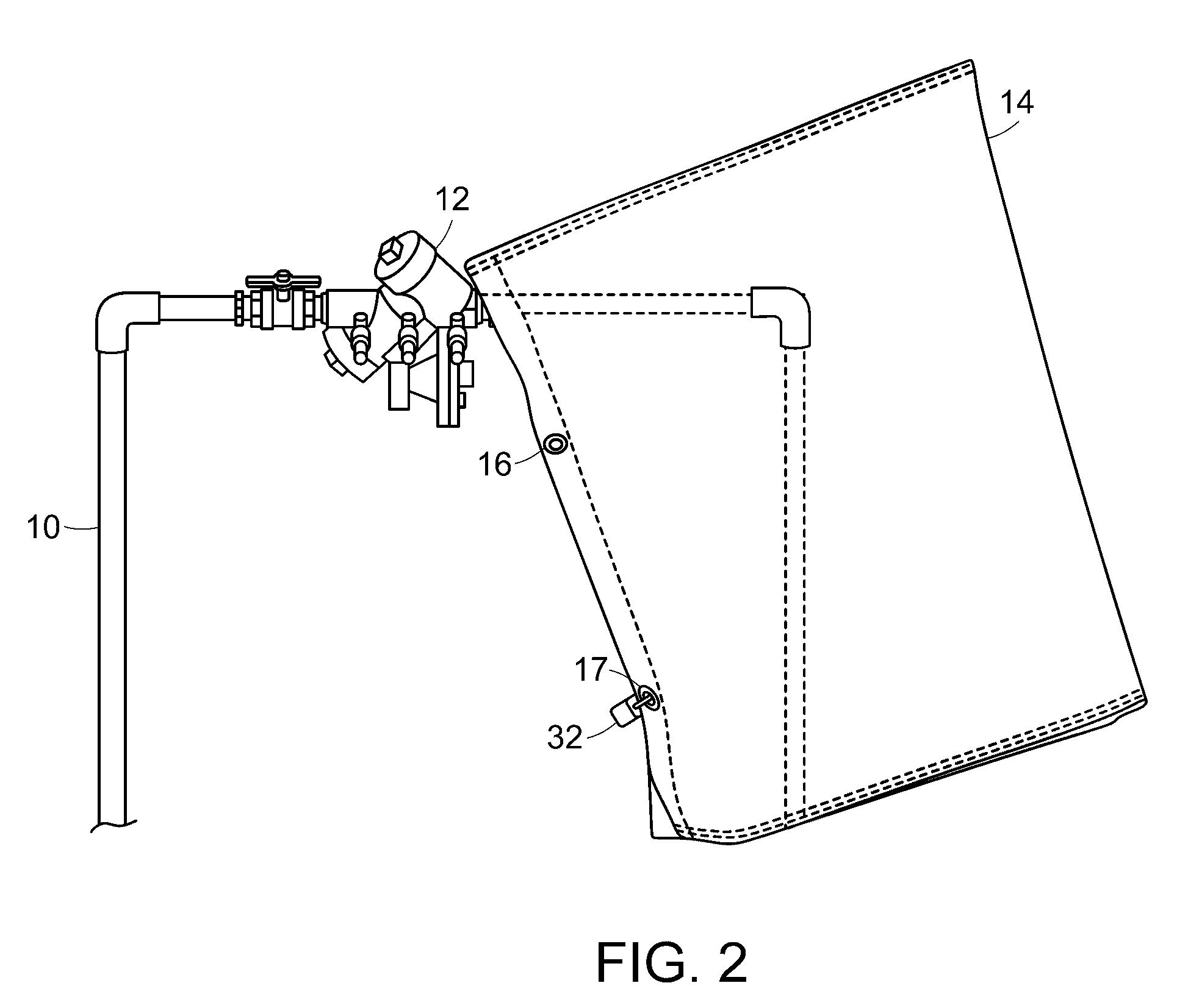
[0003]The improved thermal cover invented by the applicant provides freeze resistance when installed on backflow prevention assemblies or other liquid transmission component, systems, etc. The combination of improved insulation material and a heat / cold barrier described herein provide superior passive freeze resistance. In addition, the heat barrier component of the invention provides protection from loss of radiant heat, reflecting the otherwise lost heat back into an insulated pad thereby acting like a “heat dam” to reduce the transfer of heat into the open air.
[0004]One or more foil barriers further enhance protection against radiant heat loss. The combination of one or more foil backings attached to a structurally-strong foam layer contributes to the thermal cover's ability to maintain its shape and its' effectiveness over time as well. In addition, stitching the heat barrier and / or insulated pad components together with the outer covering also helps to maintain the positioning of the underlying components within the thermal cover thereby increasing the thermal cover's resilience and effectiveness long term. At the centerline, the insulated pad and / or heat barrier is sewn with semi-circle (e.g. or other shape such as an arch, angular, circle, etc.) to the inner covering and outer covering.
[0007]The inner covering and outer covering (i.e. of the thermal cover's wrapper) are preferably constructed of tough material, similar to that used to make truck tarps. This material resists damage when accidentally brushed by lawn mowers and other landscaping equipment. Wrapper, insulation and heat barrier material that resists moisture, mold and mildew reduces the occurrence of wet break up that would otherwise result in the insulation material lying in mounds at the lowest part of the thermal cover.

Problems solved by technology

Certain liquid transmission mechanisms and systems, piping systems and associated devices such as backflow prevention assemblies providing critically important operations may be subjected to environmental transient and / or high or low temperature extremes.
As a result, the devices are subjected to high temperature fluctuations that cause premature deterioration of the system components and other undesirable conditions.

Method used


Image

  • Thermal Cover
  • Thermal Cover
  • Thermal Cover

Examples


Embodiment Construction

[0023]Embodiments of the invention provide more effective thermal protective covering for backflow prevention assemblies, other pipe, plumbing systems and devices, test assemblies such as test cocks, irrigation, water and other systems, etc. such as for transmission of liquids. A central feature of the present invention is the employment of a heat barrier that limits heat loss that would otherwise radiate from the protected device / system into the open air. The heat barrier includes a layer of foam or other material such as bubble wrap. In addition, the layer of foam may be backed with foil on one or both sides. The foil may or may not be bonded to the foam. The foil-backed foam combination provides a barrier to radiant heat transfer exceeding the level of heat transfer protection that would otherwise be possible. The heat barrier also reflects heat back into an insulated pad component of the thermal cover as such, acting like a “heat dam” and ultimately reducing the transfer of heat...


PUM


Abstract

The invention is directed to improvement in thermal covers used to protect piping, liquid transmission, backflow prevention systems, etc. The improved thermal cover includes an insulated pad, a heat barrier and wrapper to hold the insulated pad configured in a specific fashion so as to improve freezing resistance and / or reduction of damage due to excessive heat. Padlocks, ties, etc. secure a thermal cover by means of grommets to an underlying piping, liquid transmission, backflow prevention system, etc. component. Removal of a tie permits access to the underlying components. Padlocks provide security for the thermal cover simultaneously with the access afforded due to removal of a tie. One or more foil layers further enhance protection against radiant heat loss. The combination of the one or more components of foil backing attached to structurally strong foam contributes to the thermal cover's ability to maintain its shape and it's effectiveness over time.

Description

BACKGROUND OF THE INVENTION[0001]Certain liquid transmission mechanisms and systems, piping systems and associated devices such as backflow prevention assemblies providing critically important operations may be subjected to environmental transient and / or high or low temperature extremes. These systems often operate outdoors, during the winter for example, when temperatures drop to or below freezing for brief periods of time. Alternatively these systems may operate at high temperature during summer months. Certain mechanisms such as backflow prevention assemblies used in conjunction with water supply systems may have low water flow. As a result, the devices are subjected to high temperature fluctuations that cause premature deterioration of the system components and other undesirable conditions.[0002]Since their operation is critical, it is sometimes worthwhile to provide protection from undesirable effects of the heat or cold in order to avoid the malfunction or damage to the device...

Claims


Application Information

Patent Timeline
Patent Type & Authority Applications(United States)
IPC IPC(8): E03B7/10
CPCE03B7/10
Inventor BULLER, DENNIS WILSON
Owner BULLER DENNIS WILSON
Learn More