Eureka AIR delivers breakthrough ideas for toughest innovation challenges, trusted by R&D personnel around the world.

Proton conductive hybrid material, and catalyst layer for fuel cell using the same

Inactive Publication Date: 2009-09-03
THE UNIV OF TOKYO
View PDF7 Cites 12 Cited by
  • Summary
  • Abstract
  • Description
  • Claims
  • Application Information

AI Technical Summary

Benefits of technology

[0013]An object of the present invention is to provide an organic-inorganic hybrid material which can show higher proton conductivity in a wide temperature range from low temperatures to high temperatures.
[0014]Another

Problems solved by technology

Considering the properties of proton conductive materials, in general, polymeric materials show a desirable conductivity under humidified condition; however, the disadvantages are its degradation at higher temperatures and its high resistance when it is not humidified properly.
On the other hand, inorganic conductors are thermally and mechanically more stable, but they are brittle and the pure oxides do not show high proton conductivity.
Fluorine-based ionomers, a major

Method used


Image

  • Proton conductive hybrid material, and catalyst layer for fuel cell using the same
  • Proton conductive hybrid material, and catalyst layer for fuel cell using the same
  • Proton conductive hybrid material, and catalyst layer for fuel cell using the same

Examples


Example

Example 1

1. Sol-Gel Synthesis of Re-Dispersible Zirconia Precursor Powder

[0362]Zirconia sol was prepared from zirconium alkoxide (Zirconium butoxide): A dilute solution (0.05M) of zirconium alkoxide was first made in isopropyl alcohol. During the sol preparation, a surface modifier (such as Acetyl acetone) was added dropwise to the zirconium alkoxide solution under stirring, and continued stirring for 2 hrs. The metal (M) to surface modifier (L) ratio was 1:2. 1M nitric acid solution was used as the hydrolyzing catalyst, and added to the above system under vigorous stirring, to obtain a clear, transparent, stable zirconia sol. This was further stirred for overnight. Zirconia gel was obtained by evaporating the solvent at 90° C., and was further dried at 90 / 100° C. for one day in an air oven. The dried powder was tested for its dispersion characteristics in organic solvents used for the polymer. The dynamic light scattering experiments for stokes particle size determination were carr...

Example

Example 2

Experiments

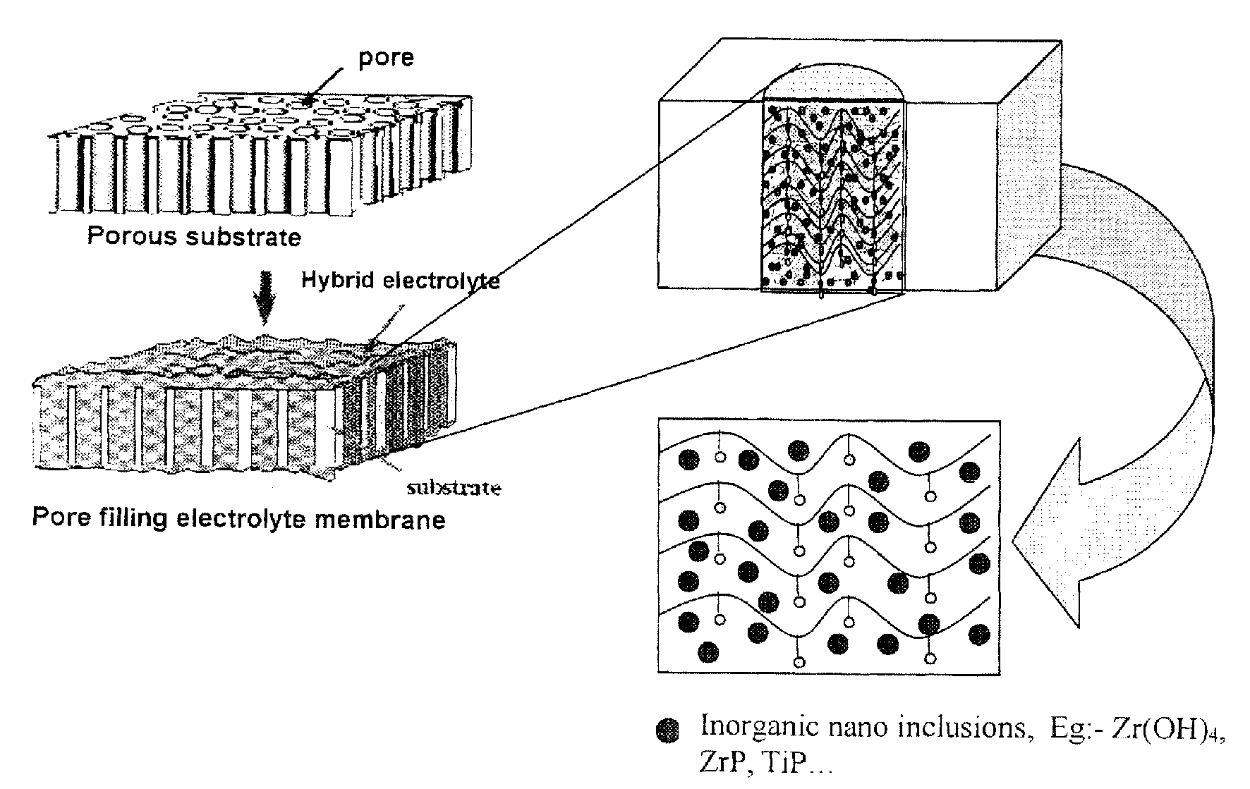
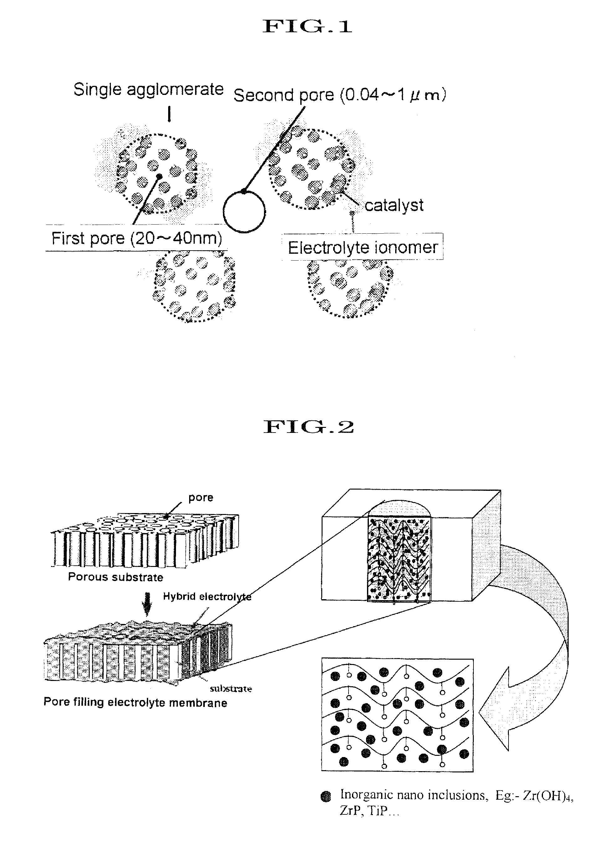
[0368]A nano-sized particle has a high surface energy, and it can form agglomerate easily with near particle. It is important that high surface area and particle to particle distance for a proton conductivity network in inorganic solid proton conductors materials. There are necessary to stabilization of particle surface. For this purpose, SPES ionomer is used as a capping agent to nano-hydrated zirconia. They attract each other because of an absorption and / or coordination force as shown in FIG. 10. And the strength of nano-hydrated zirconia and SPES is enhanced by using a reduction agent like alcohol. Because of alcohol is a poor solvent for SPES. The procedure of particle size control is as follows:

Materials:

[0369]Hydrated zirconia;

[0370]SPES ion-exchanged resin;

[0371]DMF (dimethylformamide);

[0372]Alcohol.

Procedure:

[0373]1. Weigh out 0.1375 g of 10 wt % hydrated zirconia solution dissolved in DMF in a vial container with a stirring bar.

[0374]2. Stir the solution...


PUM

PropertyMeasurementUnit
Temperatureaaaaaaaaaa
Electrical conductivityaaaaaaaaaa

Abstract

This invention provides an organic-inorganic hybrid material, which can exhibit high proton conductivity in a wide temperature range of a low temperature to a high temperature, a proton conductive material, which has a small particle diameter, that is, has a particle diameter capable of reaching pores of primary particles of carbon powder or the like, and has controlled particle diameters, a catalyst layer containing these materials for a fuel cell and an electrolyte film containing these materials for a fuel cell, and a fuel cell. The proton conductive hybrid material comprises proton conductive inorganic nanoparticles and a proton conductive polymer, wherein the Stokes particle diameter of the proton conductive hybrid material by dynamic light scattering is not more than 20 nm.

Description

BACKGROUND OF THE INVENTION[0001]1. Field of the Invention[0002]The present invention relates to a proton conductive hybrid material which comprises a proton-conductive inorganic nanoparticle and a proton-conductive polymer, and which has small-regulated particle diameter. In particular, the present invention relates to a catalyst layer for use of a fuel cell, wherein the proton conductive hybrid material, which has small-regulated particle diameter, is included in primary pores of the catalyst layer, and to a method for producing the material and the catalyst layer.[0003]2. Description of Related Art[0004]In recent years, much attention has been paid on the development and use of novel organic-inorganic nanocomposite materials as proton conductors, especially because of its possible commercial application in polymer electrolyte membrane fuel cells (PEMFC), since these materials can show high conductivity and can form thermally stable membranes at elevated temperatures.[0005]Conside...

Claims


Application Information

Patent Timeline
IPC IPC(8): H01M8/10H01M8/08
CPCH01B1/122H01M4/86H01M8/0289Y02E60/523H01M8/1048H01M8/1051H01M2300/0091H01M8/1023Y02E60/50
Inventor YAMAGUCHI, TAKEOLEE, JU MYEUNGANILKUMAR, GOPINATHAN MADHAVIKUTTY
Owner THE UNIV OF TOKYO
Why Eureka
Eureka Blog
Learn More