
Semiconductor Pressure Sensor

Active Publication Date: 2009-09-03
FUJI ELECTRIC CO LTD
View PDF8 Cites 21 Cited by
  • Summary
  • Abstract
  • Description
  • Claims
  • Application Information

AI Technical Summary

Benefits of technology

[0016]According to the present invention, the pads for wire bonding and the probe pads for characteristic confirmatory check are provided with the adhesion ensuring-diffusion preventive layer in an aluminum wiring layout and hence the gold coating applied on the outermost surface of the pads is prevented from diffusing in

Problems solved by technology

However the measure is still insufficient for the resistance of corrosion caused by nitrate ions in nitrogen oxide contained in exhaust gas.

Method used


Image

  • Semiconductor Pressure Sensor
  • Semiconductor Pressure Sensor
  • Semiconductor Pressure Sensor

Examples


first embodiment

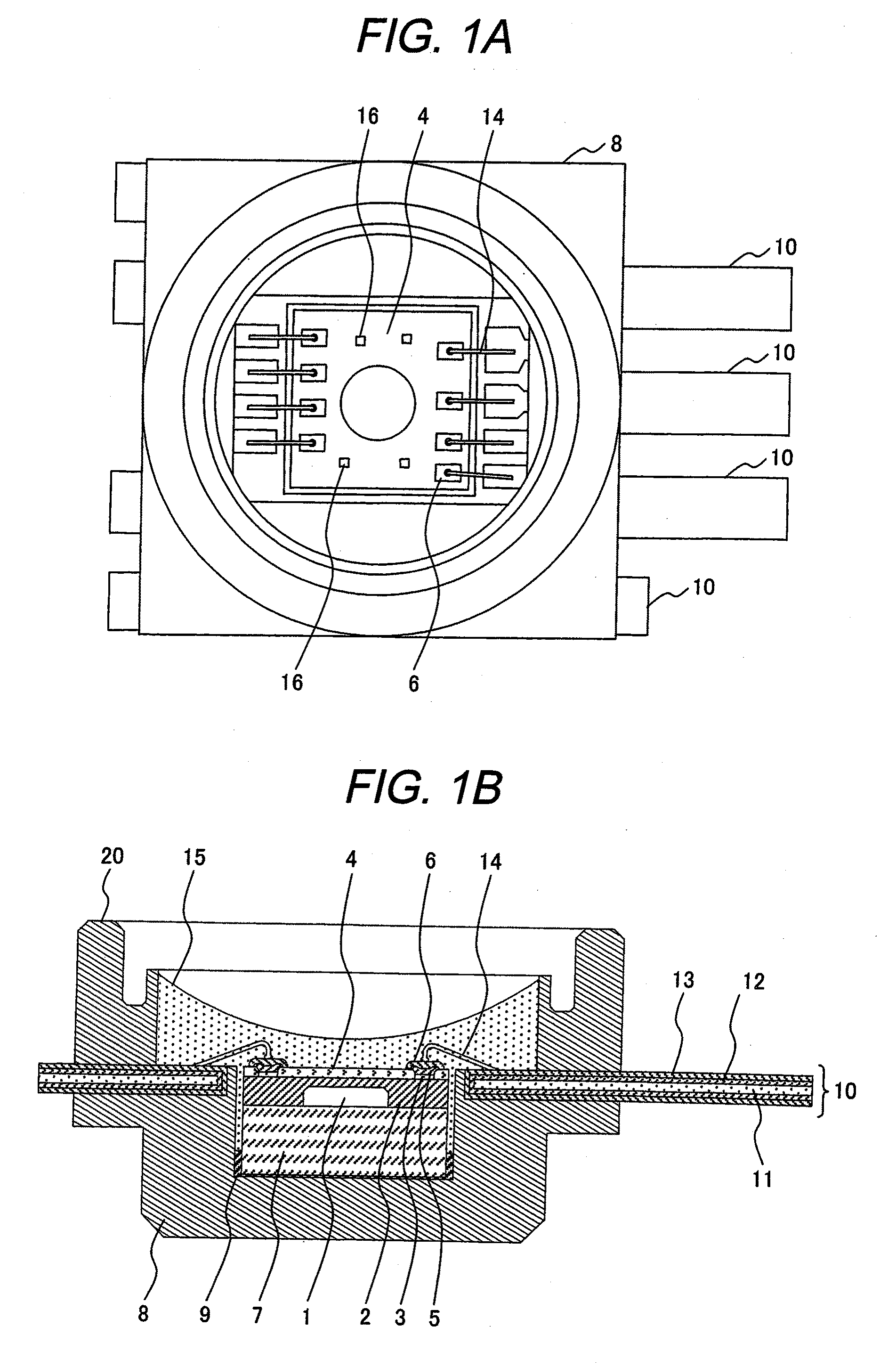
[0037]FIG. 1 comprises a front view (FIG. 1(A)) and a sectional view (FIG. 1(B)) showing a semiconductor pressure sensor submodule according to the first embodiment of the present invention. The present embodiment is the case where a pressure sensitive element of the pressure sensor is formed with a small submodule.

[0038]A diaphragm 1 made of silicon and provided with resistances (not shown in the figure) functioning as a strain gage are formed in a sensor chip 2. The strain gage-resistances and aluminum electrodes 3 to connect them are formed on the surface of the sensor chip 2. Further, the sensor chip 2 is covered with silicon nitride (SiN) 4 in order to protect the strain gage-resistances and the aluminum electrodes against a corrosive environment.

[0039]At wire bonding pads for outputting a signal from the strain gage, the aluminum electrodes are exposed usually and the signal are output to the exterior through aluminum wires or gold wires.

[0040]Each of wire bonding pads accordi...

second embodiment

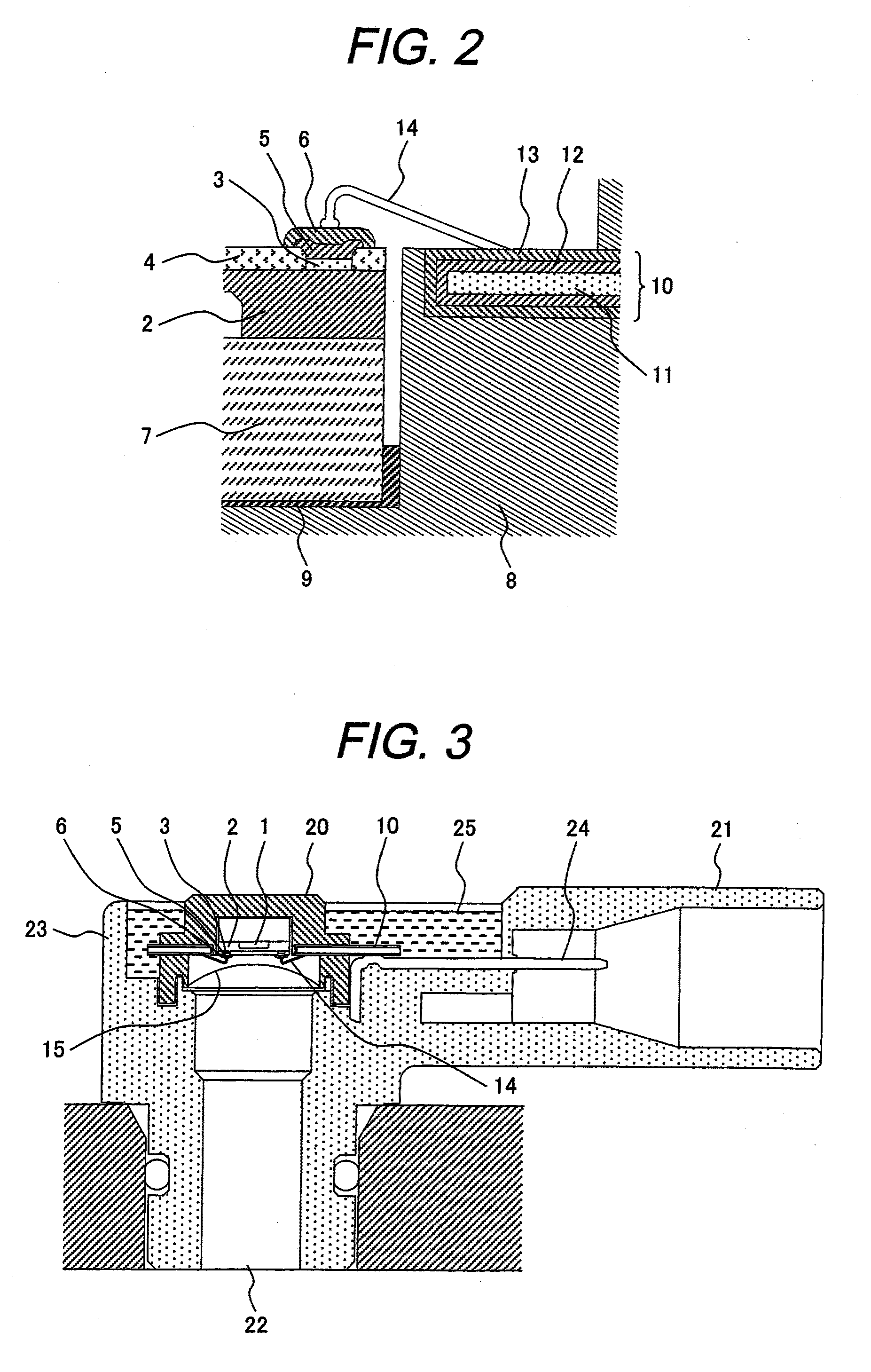
[0058]FIG. 5 is an enlarged sectional view showing a partially modified substantial part of the pressure sensor submodule shown in FIG. 2.

[0059]A gold electrode 6 of a sensor chip 2 is electrically connected to the gold-plated layer 13 of a terminal 10 with a gold wire 14 by wire bonding. By using the gold wire 14 for bonding, corrosion resistance against corrosive matters is improved. In order to prevent an adhesion ensuring-diffusion preventative layer 5 from being damaged due to the application of vibration at the bonding with the gold wire 14, parts of an aluminum electrode immediately under the part subjected to the wire bonding are cut out locally. By so doing, a titanium-tungsten layer 5 is prevented from incurring cracks when load and vibration are applied due to the bonding and the gold in the gold electrode 6 is prevented from diffusing into the aluminum electrode 3.

[0060]The shape of the aluminum electrode after locally cut may be changed variously besides the case shown ...


PUM


Abstract

An object of the present invention is to solve problems in that aluminum electrodes, aluminum wires, and I / O terminals are corroded by corrosive gasses when a pressure of a pressure medium containing corrosive matters such as exhaust gas is measured with a semiconductor sensor; and improve not only the corrosion resistance of the sensor chip but also the corrosion resistance of the portion particularly functioning as the pressure receiver.Each of the aluminum electrodes that is likely to be corroded portions is prevented from being corroded by forming a titanium-tungsten layer and gold layer on the aluminum electrode. The connecting wires are prevented from being corroded by corrosive matters by using gold wires. The I / O terminals are also prevented from being corroded by applying gold plating.

Description

TECHNICAL FIELD[0001]The present invention relates to a mounting structure for a semiconductor pressure sensor that uses semiconductor strain gages to improve corrosion resistance to corrosive gases.BACKGROUND ART[0002]A semiconductor pressure sensor using semiconductor a strain gage has been used for measurement of an intake air pressure in an automobile and others. In recent years, with the aim of improving cleanliness exhaust gas, the adoption of EGR for recirculating exhaust gas to an intake air system has been spread and a recirculation rate of EGR tends to increase particularly in an application to a diesel engine. Since a semiconductor pressure sensor for pressure measurement on the intake air system with EGR has been used in an environment where the semiconductor pressure sensor is more likely to be exposed in exhaust gas, the necessity of resistance to exhaust gas is increasing.[0003]Further, in the case of a diesel engine, the adoption of a DPF (Diesel Particulate Filter) ...

Claims


Application Information

Patent Timeline
IPC IPC(8): H01L29/02
CPCG01L15/00G01L19/0038H01L2224/45144H01L2224/45124G01L19/0627G01L19/0084G01L19/141G01L19/147H01L2224/48465H01L2924/01004H01L2924/01013H01L2924/01046H01L2924/01078H01L2924/01079H01L2924/04941H01L2924/00H01L2224/05553
Inventor KAMINAGA, TOSHIAKIHAYASHI, MASAHIDEUEYANAGI, KATUSMICHISAITO, KAZUNORINISHIKAWA, MUTSUO
Owner FUJI ELECTRIC CO LTD
Learn More